
Nissan Murano: System Description / System
- Engine Control System
- Multiport Fuel Injection System
- Electric Ignition System
- Air Conditioning Cut Control
- Automatic Speed Control Device (ascd)
- Cooling Fan Control
- Electronic Controlled Engine Mount
- Evap Orative Emission System
- Throttle Control
- Intake Valve Timing Control
- Exhaust Valve Timing Control
- Engine Protection Control at Low Engine Oil Pressure
- Fuel Filler Cap Warning System
- Warning/indicator/chime List
- Variable Induction Air System
- Integrated Control of Engine, Cvt, and Abs
- Can Communication
- Fuel Pump Control Module (fpcm)
 Structure and Operation
Positive Crankcase Ventilation (PCV)
This system returns blow-by gas to the intake manifold.The positive crankcase ventilation (PCV) valve is provided to conduct crankcase blow-by gas to the intake manifold...
 Engine Control System
System Description
SYSTEM DIAGRAMSYSTEM DESCRIPTIONECM controls the engine by various functions. Function Reference
Multiport fuel injection system
System Description
Electric ignition system
System Description
Air conditioning cut control
System Description
Automatic speed control device (ASCD)
System DescriptionSystem Description
Cooling fan control
System Description
Electronic controlled engine mount
System Description
Evaporative emission system
System Description
Throttle control
System Description
Intake valve timing control
System Description
Exhaust valve timing control
System Description
Engine protection control at low engine oil pressure
System Description
Fuel filler cap warning system
System Description
Variable induction air system
System Description
Integrated control of engine, CVT, and ABS
System Description
CAN communication
System Description
Fuel pump control module (FPCM)
System Description
Fail-safe
DTC No...
Other information:
Nissan Murano (Z52) 2015-2024 Service Manual: Light Reminder Warning
Light Reminder Warning SYSTEM DIAGRAMWARNING CHIME OPERATION CONDITIONSIf all of the following conditions are fulfilled: Operation conditions Ignition switch OFF Combination switch (Lighting switch) 1st or 2nd position Driver side door Open [front door switch LH ON] WARNING CHIME CANCEL CONDITIONSWarning is canceled if any of the following conditions are fulfilled: Operation conditions Ignition switch ON Combination switch (Lighting switch) OFF or AUTO position Driver side door Close [front door switch LH OFF] SIGNAL PATH BCM requires warning chime output to combination meter when it judges light reminder warning chime is necessary from signals below...
Nissan Murano (Z52) 2015-2024 Service Manual: Rear Door Finisher
Exploded View 1. Rear door 2. Rear door finisher 3. Inside door handle escutcheon 4. Rear power window switch 5. Pull handle cap Clip Pawl Front Removal and Installation REMOVALUsing a suitable tool release pawls and remove pull handle cap then remove rear door finisher bolt...
Categories
- Manuals Home
- Nissan Murano Owners Manual
- Nissan Murano Service Manual
- System malfunction
- How to enable/disable the LDW system
- Shift lock release
- New on site
- Most important about car
Seatback pockets
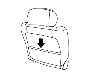
Theremaybe one or two seatback pockets located on the back of the driver and passenger seats. The pockets can be used to store maps.
WARNING

Copyright © 2026 www.nimurano.com