Nissan Murano: System / Fuel Pump Control Module (fpcm)
SYSTEM DIAGRAM
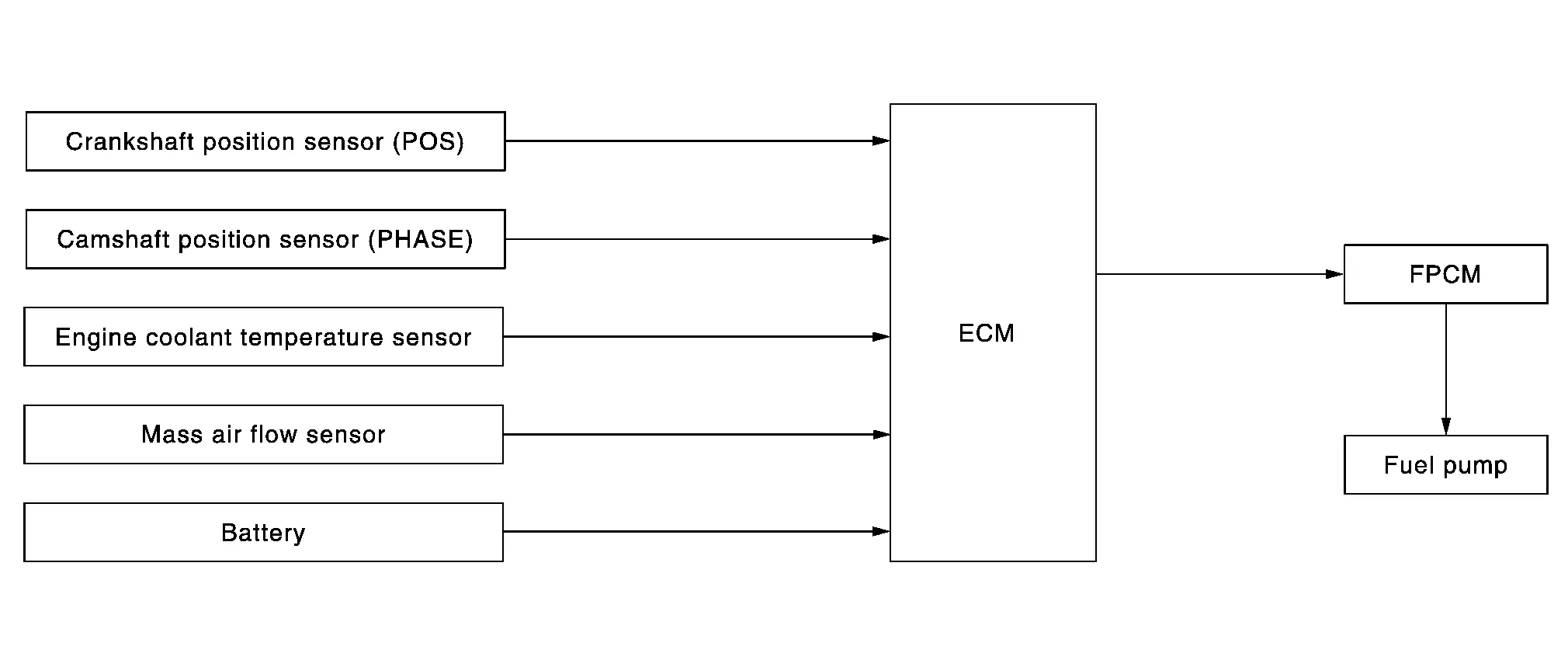
*1: ECM determines the start signal status by the signals of engine speed and battery voltage.
*2: This sensor is not used to control the engine system under normal conditions.
INPUT/OUTPUT SIGNAL CHART
| Sensor | Input signal to ECM | ECM function | Actuator |
|---|---|---|---|
| Crankshaft position sensor (POS) | Engine speed* | Fuel pump control |
FPCM ↓ Fuel pump |
| Camshaft position sensor (PHASE) | |||
| Engine coolant temperature sensor | Engine coolant temperature | ||
| Mass air flow sensor | Amount of intake air | ||
| Battery | Battery voltage* |
*: ECM determines the start signal status by the signals of engine speed and battery voltage.
SYSTEM DESCRIPTION
The fuel pump control module (FPCM) controls the discharging volume of the fuel pump by the FPCM control signals (Low/Mid/High) depending on driving conditions.
| Conditions | Amount of fuel flow | Supplied voltage |
|---|---|---|
| For 1 second after turning ignition switch ON | Low | Approximately 8.5 V |
|
High | Battery voltage 12 V |
| Except the above | Mid | Approximately 10 V |
 Can Communication
System Description
CAN (Controller Area Network) is a serial communication line for real time application. It is an on-Nissan Murano vehicle multiplex communication line with high data communication speed and excellent error detection ability...
 Operation. Automatic Speed Control Device (ascd)
Switch Name and Function
SWITCHES AND INDICATORS 1.
CRUISE indicator
2.
SET indicator
3.
CANCEL switch
4.
ON/OFF (MAIN) switch
5.
SET-
6...
Other information:
Nissan Murano (Z52) 2015-2024 Owners Manual: System malfunction
If the RAB system malfunctions, it will be turned off automatically, and the RAB system warning light will illuminate in the vehicle information display. Action to take If the warning light illuminates, park the vehicle in a safe location, turn the engine off, and restart the engine...
Nissan Murano (Z52) 2015-2024 Service Manual: Moonroof Does Not Operate Properly
Diagnosis Procedure CHECK BCM POWER SUPPLY AND GROUND CIRCUIT Check BCM power supply and ground circuit. Refer to Diagnosis Procedure. Is the inspection result normal? YES>> GO TO 2. NO>> Repair or replace malfunctioning parts. CHECK MOONROOF MOTOR ASSEMBLY POWER SUPPLY AND GROUND CIRCUIT Check moonroof motor assembly power supply and ground circuit...
Categories
- Manuals Home
- Nissan Murano Owners Manual
- Nissan Murano Service Manual
- Fuel recommendation
- Intelligent Forward Collision Warning (I-FCW)
- Shift lock release
- New on site
- Most important about car
LATCH (Lower Anchors and Tethers for CHildren) system

LATCH system lower anchor locations - bench seat
Your vehicle is equipped with special anchor points that are used with LATCH system compatible child restraints. This system may also be referred to as the ISOFIX or ISOFIX compatible system. With this system, you do not have to use a vehicle seat belt to secure the child restraint unless the combined weight of the child and child restraint exceeds 65 lbs. (29.5 kg). If the combined weight of the child and child restraint is greater than 65 lbs. (29.5 kg), use the vehicle’s seat belt (not the lower anchors) to install the child restraint. Be sure to follow the child restraint manufacturer’s instructions for installation.