Nissan Murano: System / Air Conditioning Cut Control
SYSTEM DIAGRAM
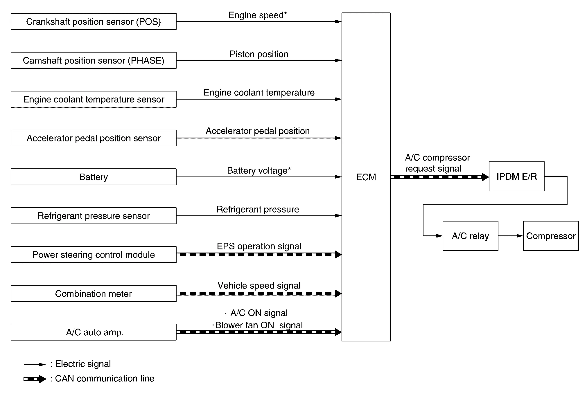
*: ECM determines the start signal status by the signals of engine speed and battery voltage.
SYSTEM DESCRIPTION
This system improves engine operation when the air conditioner is used.
Under the following conditions, the air conditioner is turned OFF.
-
When the accelerator pedal is fully depressed.
-
When cranking the engine.
-
At high engine speeds.
-
When the engine coolant temperature becomes excessively high.
-
When operating power steering during low engine speed or low Nissan Murano vehicle speed.
-
When engine speed is excessively low.
-
When refrigerant pressure is excessively low or high.
 Electric Ignition System
System Description
SYSTEM DIAGRAM*: ECM determines the start signal status by the signals of engine speed and battery voltage.SYSTEM DESCRIPTIONIgnition order: 1 - 2 - 3 - 4 - 5 - 6The ignition timing is controlled by the ECM to maintain the best air-fuel ratio for every running condition of the engine...
 Automatic Speed Control Device (ascd)
System Description
SYSTEM DIAGRAMBASIC ASCD SYSTEMRefer to Owner's Manual for ASCD operating instructions.Automatic Speed Control Device (ASCD) allows a driver to keep vehicle at predetermined constant speed without depressing accelerator pedal...
Other information:
Nissan Murano (Z52) 2015-2024 Owners Manual: Difference between predicted and actual distances
The displayed guidelines and their locations on the ground are for approximate reference only. Objects on uphill or downhill surfaces or projecting objects will be actually located at distances different from those displayed in the monitor relative to the guidelines (refer to illustrations)...
Nissan Murano (Z52) 2015-2024 Service Manual: Additional Service When Replacing Transaxle Assembly
Description Perform the following work after the transaxle assembly is replaced. For work procedure, refer to Work Procedure.NOTE: The CD provided with the new transaxle assembly contains important calibration data that must be installed with CONSULT after installation of the new transaxle assembly...
Categories
- Manuals Home
- Nissan Murano Owners Manual
- Nissan Murano Service Manual
- Intelligent Forward Collision Warning (I-FCW)
- GAS STATION INFORMATION
- Settings
- New on site
- Most important about car
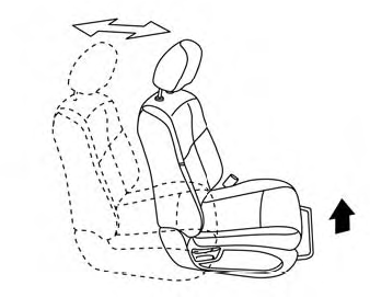
Front manual seat adjustment (if so equipped)
Your vehicle seats can be adjusted manually. For additional information about adjusting the seats, refer to the steps outlined in this section.
Forward and backward