Nissan Murano: System / Engine Protection Control at Low Engine Oil Pressure
SYSTEM DIAGRAM
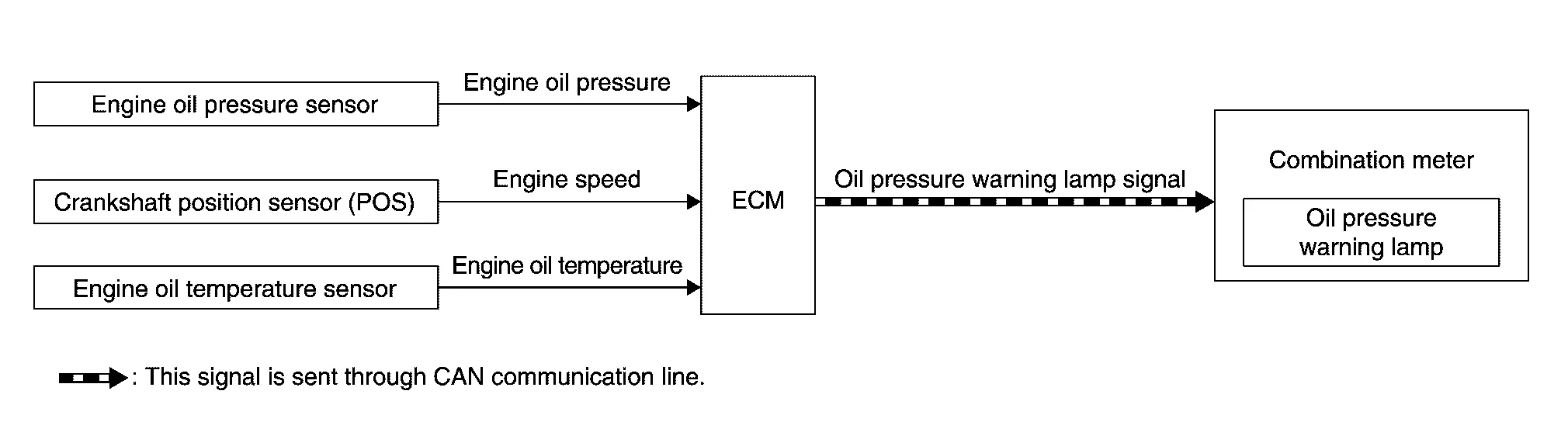
SYSTEM DESCRIPTION
-
The engine protection control at low engine oil pressure warns the driver of a decrease in engine oil pressure by the oil pressure warning lamp before the engine becomes damaged.
-
When detecting a decrease in engine oil pressure at an engine speed less than 1,000 rpm, ECM transmits an oil pressure warning lamp signal to the combination meter. The combination meter turns ON the oil pressure warning lamp, according to the signal.
-
When detecting a decrease in engine oil pressure at an engine speed 1,000 rpm or more, ECM transmits an oil pressure warning lamp signal to the combination meter.
The combination meter turns ON the oil pressure warning lamp, according to the signals. When detecting a decrease in engine oil pressure, ECM cuts fuel if the engine speed exceeds the specified value.
| Decrease in engine oil pressure | Engine speed | Combination meter | Fuel cut |
|---|---|---|---|
| Oil pressure warning lamp | |||
| Detection | Less than 1,000 rpm | ON* | NO |
| 1,000 rpm or more | ON | YES |
*: When detecting a normal engine oil pressure, ECM turns OFF the oil pressure warning lamp.
 Exhaust Valve Timing Control
System Description
SYSTEM DIAGRAMINPUT/OUTPUT SIGNAL CHART Sensor Input signal to ECM ECM function Actuator
Crankshaft position sensor (POS)
Engine speed and piston position
Exhaust valve timing control
Exhaust valve timing control solenoid valve
Camshaft position sensor (PHASE)
Engine oil temperature sensor
Engine oil temperature
Exhaust valve timing control position sensor
Exhaust valve timing signal
Combination meter
CAN communication
Nissan Murano Vehicle speed signal
SYSTEM DESCRIPTIONThis mechanism hydraulically controls cam phases continuously with the fixed operating angle of the exhaust valve...
 Fuel Filler Cap Warning System
System Description
SYSTEM DIAGRAMSYSTEM DESCRIPTIONThe fuel filler cap warning system alerts the driver to the prevention of the fuel filler being left uncapped and malfunction occurrences after refueling, by turning ON the fuel filler cap warning display on the combination meter...
Other information:
Nissan Murano (Z52) 2015-2024 Service Manual: Power Supply and Ground Circuit. Audio Unit
Diagnosis Procedure CHECK FUSE Check that the following fuses are not blown: Terminal No. Signal name Fuse No. Capacity 7 ACC power supply 7 10 A 17 Ignition power supply 29 10 A 19 Battery power supply 15 20 A Are the fuses blown? YES>> Replace the blown fuse after repairing the affected circuit...
Nissan Murano (Z52) 2015-2024 Service Manual: How to Read Wiring Diagrams
Connector Symbols Most connector symbols in wiring diagrams are shown from the terminal side. Connector symbols shown from the terminal side are enclosed by a single line and followed by the direction mark. Connector symbols shown from the harness side are enclosed by a double line and followed by the direction mark...
Categories
- Manuals Home
- Nissan Murano Owners Manual
- Nissan Murano Service Manual
- Shift lock release
- Jacking up vehicle and removing the damaged tire
- Settings
- New on site
- Most important about car
Luggage hooks

When securing items using luggage hooks located on the back of the seat or side finisher do not apply a load over more than 6.5 lbs. (29 N) to a single hook.
The luggage hooks that are located on the floor should have loads less than 110 lbs. (490 N) to a single hook.