Nissan Murano: Removal and Installation / Water Hose
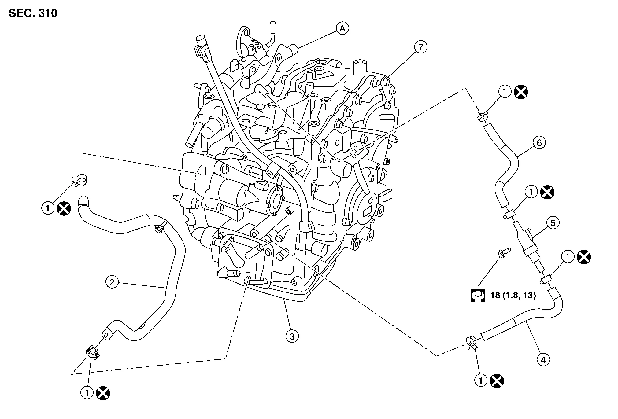
| 1. | Hose clamp | 2. | CVT water hose A | 3. | Transaxle assembly |
| 4. | CVT water hose B | 5. | Heater thermostat | 6. | CVT water hose C |
| 7. | Transaxle assembly | A. | Water outlet |
REMOVAL
WARNING:
Do not remove the radiator cap when the engine is hot. Serious burns could occur from high pressure engine coolant escaping from the radiator. Wrap a thick cloth around the cap. Slowly turn it a quarter turn to allow built-up pressure to escape. Carefully remove the cap by turning it all the way.
CAUTION:
Perform this step when engine is cold.
 NOTE:
NOTE:
When removing components such as hoses, tubes/lines, etc., cap or plug openings to prevent fluid from spilling.
Drain engine coolant from radiator. Refer to Changing Engine Coolant.
Remove front air duct. Refer to Exploded View.
Remove hose clamps, and remove CVT water hose A.
Remove hose clamps, and remove CVT water hose B.
Remove hose clamps, and remove CVT water hose C.
INSTALLATION
Installation is in the reverse order of removal.
CAUTION:
-
Do not reuse hose clamp.
-
Hose clamp should not interfere with the spool or bulge.
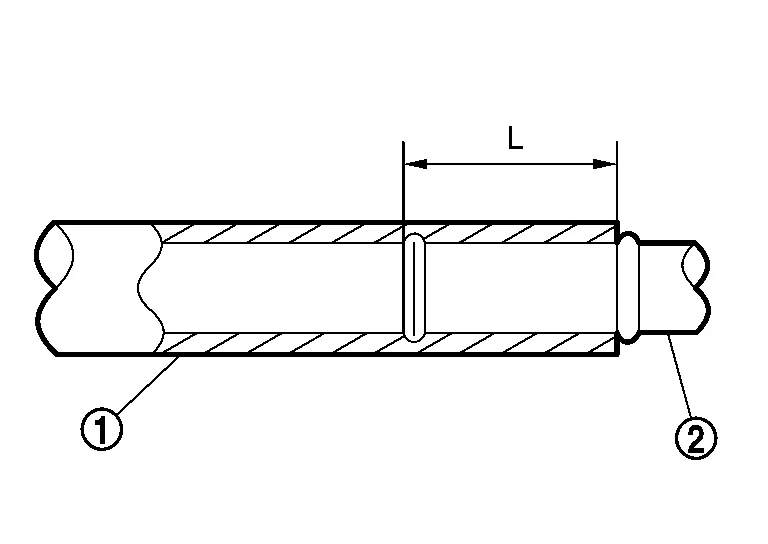
*Refer to the following when installing CVT water hose.
| Water hose (1) | Installation side tube (2) | Direction of paint mark | Hose insertion depth |
|---|---|---|---|
| CVT water hose A | Water outlet | Upward | End reaches the 2-stage bulge. |
| CVT oil warmer | Frontward | ||
| CVT water hose B | CVT oil warmer | Frontward | |
| Heater thermostat | Align with the mark on the heater thermostat side | ||
| CVT water hose C | Heater thermostat | Align with the mark on the heater thermostat side | End reaches the expansion part. |
| Water outlet | Upward | End reaches the 2-stage bulge. |
| CVT Water hose (1) | Installation side tube (2) | Hose clamp (3) | |
|---|---|---|---|
| Direction of tab* | Clamping position* | ||
| CVT Water hose A | Water outlet | C | A: 5-7 mm (0.20 - 0.28 in) (L) from hose end. |
| CVT oil warmer | J | ||
| CVT Water hose B | CVT oil warmer | H | B: Align with the paint mark (C) as shown. |
| Heater thermostat | A | ||
| CVT Water hose C | Heater thermostat | A | |
| Water outlet | G | ||
*Refer to the following when installing hose clamps.

-
The illustrations indicate the view from the hose ends.
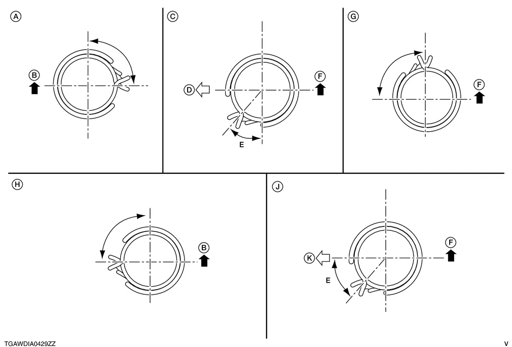
B. Front of Nissan Murano vehicle D. Vehicle right E. 45° F. Top of Nissan Murano vehicle K. Front of vehicle -
When installing hose clamps, the center line of each clamp tab should be positioned as shown.
Start and warm up the engine.
Visually check that there is no leakage of engine coolant and CVT fluid.
 Differential Side Oil Seal
Exploded View
1.
Transaxle assembly
2.
Differential side oil seal (left side)
3.
Differential side oil seal (right side) (FWD models only)
: Apply CVT fluid
Removal and Installation
REMOVALRemove front drive shaft...
 Fluid Cooler Hose
Exploded View
1.
Transaxle assembly
2.
Hose clamp
3.
CVT fluid cooler hose A
4.
Hose clip
5.
CVT fluid cooler hose B
6.
Connector tube
7...
Other information:
Nissan Murano (Z52) 2015-2024 Service Manual: Front Auxiliary Input Jacks
Diagnosis Procedure AUX JACKCHECK AUX JACK HARNESS CONTINUITY Ignition switch OFF. Disconnect audio unit connector and front auxiliary input jacks connector. Check continuity between audio unit connector and front auxiliary input jacks connector...
Nissan Murano (Z52) 2015-2024 Owners Manual: Distance To Empty (DTE)
Displays the estimated distance the vehicle can be driven before refueling. The value is calculated based on recent fuel economy, the amount of fuel remaining in the fuel tank, and the actual fuel consumption. Changes in driving patterns or conditions can cause the DTE value to vary...
Categories
- Manuals Home
- Nissan Murano Owners Manual
- Nissan Murano Service Manual
- Passenger compartment
- Memory storage function (key-link)
- Checking engine oil level
- New on site
- Most important about car
Unfastening the seat belts. Checking seat belt operation
Unfastening the seat belts

To unfasten the seat belt, press the button
on the buckle  . The seat belt
automatically
retracts.
. The seat belt
automatically
retracts.