Nissan Murano: Removal and Installation / Fluid Cooler Hose
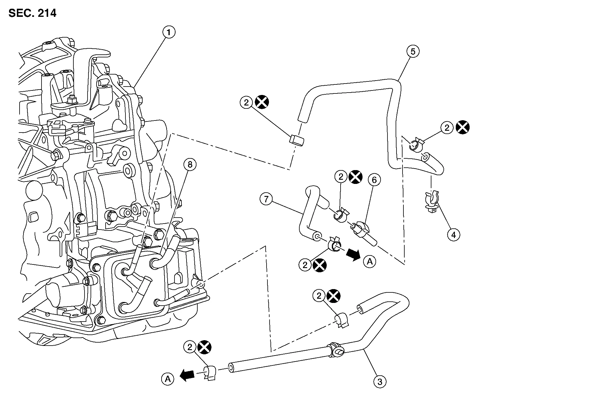
| 1. | Transaxle assembly | 2. | Hose clamp | 3. | CVT fluid cooler hose A |
| 4. | Hose clip | 5. | CVT fluid cooler hose B | 6. | Connector tube |
| 7. | CVT fluid cooler hose C | 8 | Oil warmer | A. | To radiator. Refer to Exploded View. |
REMOVAL
 NOTE:
NOTE:
When removing components such as hoses, tubes/lines, etc., cap or plug openings to prevent fluid from spilling.
Drain engine coolant from radiator. Refer to Changing Engine Coolant.
Remove front air duct. Refer to Exploded View.
Remove hose clamps and remove CVT fluid cooler hose A.
Remove hose clamps and remove CVT fluid cooler hose B and CVT fluid cooler hose C.
Remove hose clamps and remove CVT fluid cooler hose B from CVT fluid cooler hose C (if necessary).
Remove CVT fluid cooler tube A and CVT fluid cooler tube B.
INSTALLATION
Installation is in the reverse order of removal.
CAUTION:
-
Do not reuse hose clamps.
-
Hose clamps should not interfere with the spool or bulge.
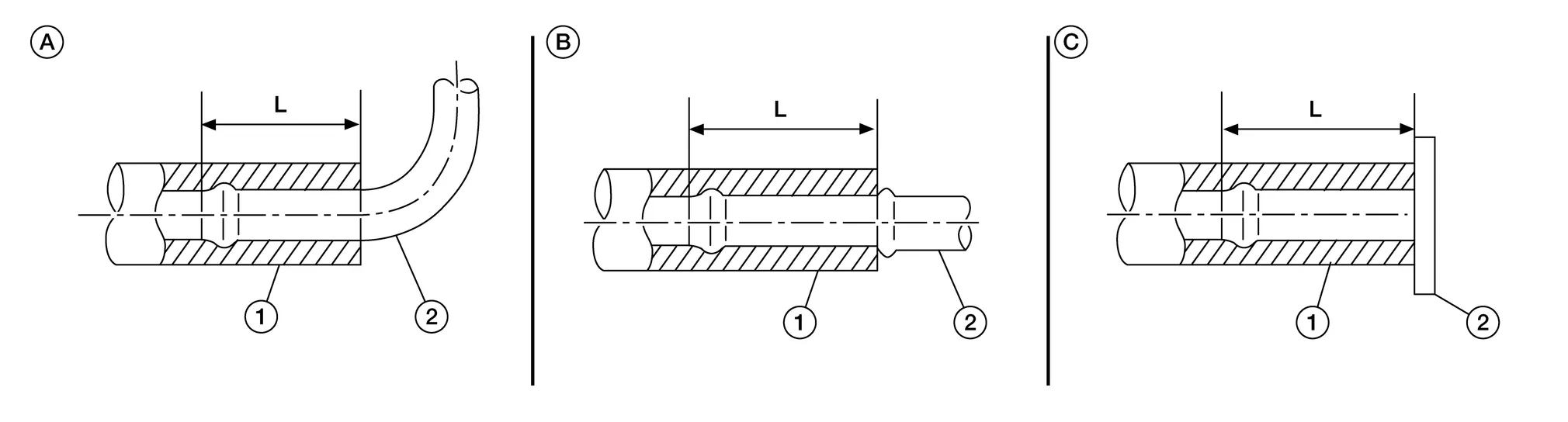
*Refer to the following when installing CVT fluid cooler hoses
| Hose name (1) | Installation side tube (2) | Direction of paint mark | Hose insertion depth (L) |
|---|---|---|---|
| CVT fluid cooler hose A | CVT oil warmer | Downward | B: End reaches the 2-step bulge. |
| Radiator | Downward | A: End reaches the radius curve end. | |
| CVT fluid cooler hose B | Connector tube | Upward | B: End reaches the spool |
| CVT oil warmer | Frontward | A: End reaches the radius curve end. | |
| CVT fluid cooler hose C | Radiator | Upward | C: Insert the hose until hose touches the radiator. |
| Connector tube | Upward | B: End reaches the spool |
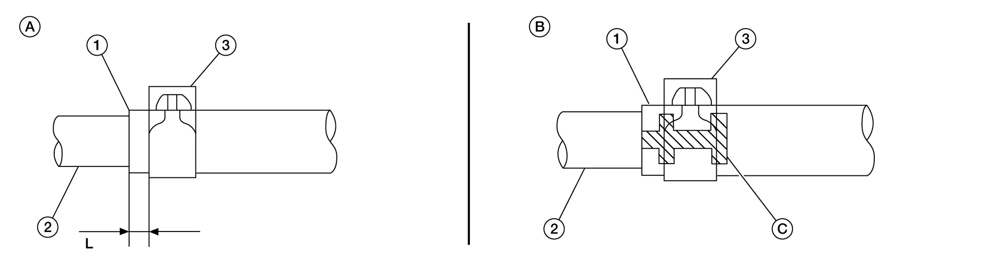
*Refer to the following when installing CVT fluid cooler hoses
| Hose name (1) | Installation side tube (2) | Hose clamp (3) | |
|---|---|---|---|
| Direction of tab | Clamping position | ||
| CVT fluid cooler hose A | CVT oil warmer | B | B: Align with the paint mark (C) as shown in the figure. |
| Radiator | B | A: 3 - 7 mm (0.12 - 0.28 in) (L) from hose end | |
| CVT fluid cooler hose B | Connector tube | A | B: Align with the paint mark (C) as shown in the figure. |
| CVT oil warmer | C | A: 3 - 7 mm (0.12 - 0.28 in) (L) from hose end | |
| CVT fluid cooler hose C | Radiator | A | |
| Connector tube | A | ||
*: Refer to the illustrations for the specific position of each hose clamp tab.
-
The illustrations indicate the view from the hose ends.
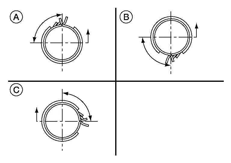
-
When installing hose clamps the center line of each clamp tab should be positioned as shown.
(A, B) : Points to top of Nissan Murano vehicle (C) : Points to front of vehicle
INSPECTION AFTER INSTALLATION
Check for CVT fluid leakage. Refer to Inspection.
ADJUSTMENT AFTER INSTALLATION
Adjust CVT fluid level. Refer to Adjustment.
 Water Hose
Exploded View
1.
Hose clamp
2.
CVT water hose A
3.
Transaxle assembly
4.
CVT water hose B
5.
Heater thermostat
6.
CVT water hose C
7...
 Cvt Oil Warmer
Exploded View
1.
Transaxle assembly
2.
CVT oil warmer
Removal and Installation
REMOVALWARNING:
Do not remove the radiator cap when the engine is hot...
Other information:
Nissan Murano (Z52) 2015-2024 Service Manual: Immu
CONSULT Function (BCM - IMMU) ECU IDENTIFICATIONThe BCM part number is displayed.SELF DIAGNOSTIC RESULTRefer to DTC Index.DATA MONITOR Monitor Item [Unit] Description CONFRM ID ALL [Yet/DONE] Switches to DONE when an Intelligent Key is registered...
Nissan Murano (Z52) 2015-2024 Owners Manual: Seat belt with pretensioner(s) (front and rear outboard seats)
WARNING The pretensioner(s) cannot be reused after activation. They must be replaced together with the retractor and buckle as a unit. If the vehicle becomes involved in a collision but pretensioner(s) are not activated, be sure to have the pretensioner system checked and, if necessary, replaced...
Categories
- Manuals Home
- Nissan Murano Owners Manual
- Nissan Murano Service Manual
- Fuel recommendation
- Settings
- All-Wheel Drive (AWD) (if so equipped)
- New on site
- Most important about car
Luggage hooks

When securing items using luggage hooks located on the back of the seat or side finisher do not apply a load over more than 6.5 lbs. (29 N) to a single hook.
The luggage hooks that are located on the floor should have loads less than 110 lbs. (490 N) to a single hook.