Nissan Murano: Automatic drive positioner (if so equipped) / Memory storage function (key-link)
Use the following process to setup key-link:
- Unlock the vehicle with the desired Intelligent Key while the ignition is OFF.
- Place the ignition in the ON position.
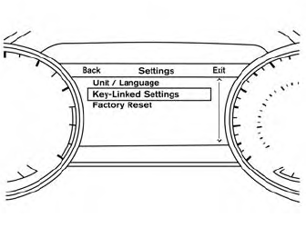
- Within the “Settings” menu of the vehicle information display, select “Key- Linked Settings” and press the OK button on the steering switch.
- While in the menu, press the OK button on the steering switch to turn the system ON/OFF.
Once step 4 is completed, every time the ignition is switched from ON to OFF, the memory positions of the driver’s seat, automatic steering wheel (if so equipped) and the outside mirrors are linked to the Intelligent Key.
Follow the same procedure if you want to link the 2nd, 3rd or 4th Intelligent Key.
NOTE:
If new memory positions are set prior to turning the ignition from ON to OFF, the previously linked memory positions for the respective key will be overwritten by new positions.
Recalling Intelligent Key memory positions
If the “Key-Linked Settings” are enabled in the vehicle information display for that particular key, every time you enter the vehicle the driver’s seat, automatic steering wheel (if so equipped), and outside mirrors will automatically move to the driver’s last position of the respective Intelligent Key.
NOTE:
The key-linked memory positions can be different fromthe positions stored in the memory switch (1 or 2).
 Automatic drive positioner (if so equipped)
The automatic drive positioner system has
three features:
Memory storage function (key-link)
Memory storage function (switch)
Entry/exit function
Key-link, when enabled, automatically retains
the driver’s last seat, automatic steering
wheel, and outside mirror positions for
that specific key when the ignition is turned
from ON to OFF...
 Memory storage function (switch)
Use the following process to manually store
the two memory positions in the switch:
The vehicle should be stopped while
setting the memory.
Adjust the driver’s seat, steering columnand
outside mirrors to the desired
positions by manually operating each
adjusting switch...
Other information:
Nissan Murano (Z52) 2015-2024 Service Manual: Glass Lid
Exploded View 1. Panoramic roof glass 2. Moonroof drain 3. Wind deflector 4. Glass lid 5. Side trim covers (LH/RH) 6. Front drain hose (LH/RH) 7. Moonroof motor assembly 8. Sunshade motor assembly 9. Moonroof front bracket (LH/RH) 10...
Nissan Murano (Z52) 2015-2024 Service Manual: Chime Does Not Sound
Diagnosis Procedure The warning chime may not sound in some cases when there is a short distance between vehicles. Some examples are: When the vehicles are traveling at the same speed and the distance between vehicles is not changing. When the Nissan Murano vehicle ahead is traveling faster and the distance between vehicles is increasing...
Categories
- Manuals Home
- Nissan Murano Owners Manual
- Nissan Murano Service Manual
- All-Wheel Drive (AWD) (if so equipped)
- Warning lights
- GAS STATION INFORMATION
- New on site
- Most important about car
Luggage hooks

When securing items using luggage hooks located on the back of the seat or side finisher do not apply a load over more than 6.5 lbs. (29 N) to a single hook.
The luggage hooks that are located on the floor should have loads less than 110 lbs. (490 N) to a single hook.