Nissan Murano: Removal and Installation / Tcu
REMOVAL
CAUTION:
Before replacing TCU, perform “ADDITIONAL SERVICE WHEN REPLACING TCU”. For details, refer to Description.
Remove the cluster lid D. Refer to Removal and Installation.
Remove the A/C switch assembly. Refer to Removal and Installation.
Remove the TCU mounting screws  .
.
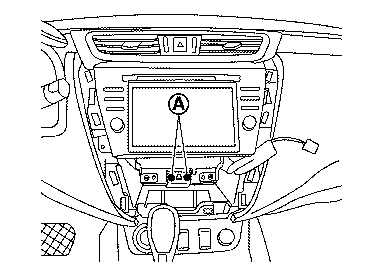
Disconnect the harness connector, and then remove the TCU.
INSTALLATION
Installation is in the reverse order of removal.
CAUTION:
After installation, perform “ADDITIONAL SERVICE WHEN REPLACING TCU”. For details, refer to Description.
 Av Control Unit
Exploded View
1.
AV control unit bracket (RH)
2.
AV control unit
3.
AV control unit bracket (LH)
4.
A/C auto amp.
Removal and Installation
REMOVALCAUTION:
Before disconnecting the AV control unit and battery terminals, turn the ignition switch OFF and wait at least 30 seconds...
 Microphone
Removal and Installation
REMOVALRemove the map lamp assembly. Refer to Removal and Installation.
Remove the microphone connector from the map lamp assembly ...
Other information:
Nissan Murano (Z52) 2015-2024 Owners Manual: Seat belts
The seat belts can be cleaned by wiping them with a sponge dampened in a mild soap solution. Allow the belts to dry completely in the shade before using them. For additional information, refer to “Seat belt maintenance” in the “Safety—Seats, seat belts and supplemental restraint system” section of this manual...
Nissan Murano (Z52) 2015-2024 Service Manual: U111a Rear Camera Image Signal Circuit
DTC Description DTC DETECTION LOGIC DTC No. CONSULT screen terms (Trouble diagnosis content) DTC detection condition U111A REAR CAMERA IMAGE SIGNAL (CAN COMM CIRCUIT) Diagnosis condition When ignition switch is ON Signal (terminal) Rear camera image signal (terminal 20) Threshold Rear camera image signal circuit is shorted or open Diagnosis delay time — POSSIBLE CAUSE Rear camera image signal circuit Around view monitor control unit Rear camera FAIL-SAFECamera image is not displayed (gray screen display) DTC Confirmation Procedure PERFORM DTC CONFIRMATION PROCEDURE CONSULT Ignition switch ON...
Categories
- Manuals Home
- Nissan Murano Owners Manual
- Nissan Murano Service Manual
- Warning lights
- Checking engine oil level
- How to enable/disable the LDW system
- New on site
- Most important about car
Driver and passenger supplemental knee air bag

Driver’s side
The knee air bag is located in the knee bolster, on the driver’s and passenger’s side. All of the information, cautions and warnings in this manual apply and must be followed. The knee air bag is designed to inflate in higher severity frontal collisions, although it may inflate if the forces in another type of collision are similar to those of a higher severity frontal impact. It may not inflate in certain collisions.

Passenger’s side