Nissan Murano: System Description / System
SYSTEM DIAGRAM
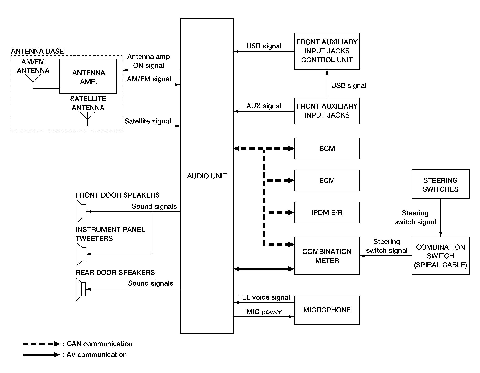
Audio Unit Input Signal (AV Communication)
| Transmit unit | Signal name |
|---|---|
| Combination meter | Steering switch signal |
Audio Unit Input Signal (CAN Communication)
| Transmit unit | Signal name |
|---|---|
| BCM | Door switches state signal |
| Combination meter |
|
| ECM | Engine RPM Signal |
| IPDM E/R | Battery voltage signal |
AUDIO SYSTEM
The audio system consists of the following components:
-
Audio unit
-
Instrument panel tweeters
-
Front door speakers
-
Rear door speakers
-
Front auxiliary input jacks
-
Front auxiliary input jacks control unit
-
Microphone
-
Steering switches
-
Combination meter
-
Combination switch (spiral cable)
-
Accessory relay-2
-
Antenna base (AM/FM antenna, antenna amp. and satellite antenna)
When the audio system is on:
-
AM/FM signals received by the AM/FM antenna are amplified by the antenna amp. and sent to the audio unit. The audio unit then sends audio signals to the speakers.
-
Satellite signals received by the satellite antenna are sent to the audio unit. The audio unit then sends audio signals to the speakers.
Refer to Owner's Manual for audio system operating instructions.
HANDS-FREE PHONE SYSTEM
System Operation
 NOTE:
NOTE:
Cellular telephones must have their wireless connection set up (paired) before using the Bluetooth® telephone system.
The Bluetooth® telephone system allows users who have a Bluetooth® cellular telephone to make a wireless connection between their cellular telephone and the audio unit. Hands-free cellular telephone calls can be sent and received. Some Bluetooth® cellular telephones may not be recognized by the audio unit. When a cellular telephone or the audio unit is replaced, the telephone must be paired with the audio unit. Different cellular telephones may have different pairing procedures, refer to the cellular telephone operating manual.
Refer to the Owner's Manual for Bluetooth® telephone system operating instructions.
Audio Unit
When the ignition switch is turned ON, the audio unit will power up. During power up, the audio unit is initialized and performs various self-checks. Initialization may take up to 20 seconds.
Steering Switches
When buttons on the steering switches are pushed, the resistance in steering switch circuits change, depending on which button is pushed.
The following functions can be performed using the steering switches:
-
Initiate self-diagnosis of the Bluetooth® telephone system
-
Start a voice recognition session
-
Answer and end telephone calls
-
Adjust the volume of calls
-
Record memos
Microphone
The microphone is located in the roof in the map lamp assembly. The microphone sends a signal to the audio unit.
SATELLITE RADIO FUNCTION
-
Satellite radio function is built into audio unit.
-
Sound signal (satellite radio) is received by satellite antenna and transmitted to audio unit. Audio unit outputs sound signal to each speaker.
FRONT AUXILIARY INPUT JACKS FUNCTION
-
Sound and data signals are transmitted from USB interfaces to the front auxiliary input jacks control unit, then the audio unit and output to each speaker.
-
Sound signals are transmitted from AUX jack to the audio unit and output to each speaker.
SPEED SENSITIVE VOLUME SYSTEM
-
Volume level of this system goes up and down automatically in proportion to the vehicle speed.
-
The control level can be selected by the customer.
 Component Parts. Display Audio System
Component Parts Location
No. Component Function
1.
Rear door speaker RH
Refer to Speakers.
2.
Microphone
Refer to Microphone.
3.
Front door speaker RH
Refer to Speakers...
 Diagnosis System (audio Unit)
Description
The audio unit on board diagnosis performs the following functions listed in the table below: Mode Description
Self Diagnosis
Audio system diagnosis...
Other information:
Nissan Murano (Z52) 2015-2024 Owners Manual: Maintenance schedules
To help ensure smooth, safe and economical driving, NISSAN provides two maintenance schedules that may be used, depending upon the conditions in which you usually drive. These schedules contain both distance and time intervals, up to 120,000 miles (192,000 km)/144 months...
Nissan Murano (Z52) 2015-2024 Service Manual: Ducts and Grilles
Exploded View FRONT 1. Defroster nozzle 2. Side defroster duct (LH) 3. Center ventilator duct 4. Heating and cooling unit 5. Front floor connecting duct (LH) 6. Front floor duct (LH) 7. Front floor duct nozzle (LH) 8. Spacer 9...
Categories
- Manuals Home
- Nissan Murano Owners Manual
- Nissan Murano Service Manual
- Fuel recommendation
- Checking engine oil level
- Passenger compartment
- New on site
- Most important about car
Unfastening the seat belts. Checking seat belt operation
Unfastening the seat belts

To unfasten the seat belt, press the button
on the buckle  . The seat belt
automatically
retracts.
. The seat belt
automatically
retracts.