Nissan Murano: System Description / Component Parts. Display Audio System
| No. | Component | Function |
|---|---|---|
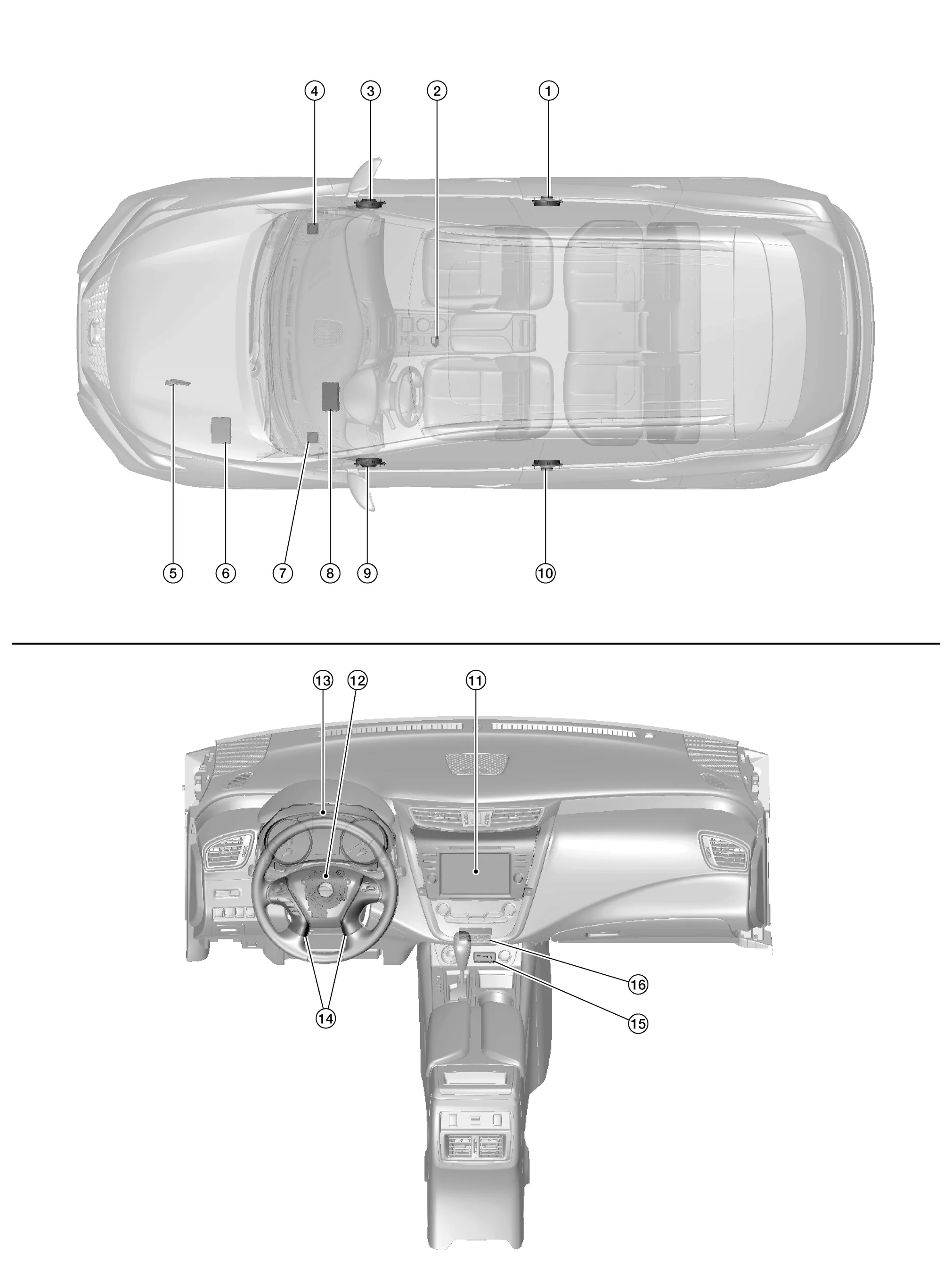
| 1. | Rear door speaker RH | Refer to Speakers. |
| 2. | Microphone | Refer to Microphone. |
| 3. | Front door speaker RH | Refer to Speakers. |
| 4. | Instrument panel tweeter RH | |
| 5. | ECM (Engine Control Module) |
Provides audio unit with engine RPM signal via CAN communication. Refer to Component Parts Location for detailed component location. |
| 6. | IPDM E/R (Intelligent Power Distribution Module Engine Room) |
Provides audio unit with battery voltage signal via CAN communication. Refer to Component Parts Location for detailed component location. |
| 7. | Instrument panel tweeter LH | Refer to Speakers. |
| 8. | BCM (Body Control Module) |
Provides audio unit with door switches state signals via CAN communication. Refer to Component Parts Location for detailed component location. |
| 9. | Front door speaker LH | Refer to Speakers. |
| 10. | Rear door speaker LH | |
| 11. | Audio unit | Refer to Audio Unit. |
| 12. | Combination switch (spiral cable) | Refer to Combination Switch (Spiral Cable). |
| 13. | Combination meter | Refer to Combination Meter. |
| 14. | Steering switches | Refer to Steering Switches. |
| 15. | Front auxiliary input jacks | Refer to Front Auxiliary Input Jacks. |
| 16. | Front auxiliary input jacks control unit | Refer to Front Auxiliary Input Jacks Control Unit. |
-
A 8-inch color display with multi-touch control, an AM/FM HD electronic tuner radio with RDS, CD drive, audio amplifier and camera controller are integrated into the audio unit.

-
The 8-inch color display is a high resolution monitor that includes touch panel functions.
-
Music files stored in iPod®*/USB memory can be played using the separate USB interface.
-
Music files stored in an external audio device can be played using the separate AUX input jack.
*: iPod® is a registered trademark of Apple, Inc. All rights reserved.
INSTRUMENT PANEL TWEETER
-
5.01 cm (2 in) tweeters are installed in the top corners of the instrument panel.

-
Sound signals generated by the audio unit output high range sounds.
FRONT DOOR SPEAKER
-
16.5 cm (6.5 in) speakers are installed in the bottom of the front doors.

-
Sound signals generated by the audio unit output low range sounds.
REAR DOOR SPEAKER
-
16.5 cm (6.5 in) speakers are installed in the bottom of the rear doors.
-
Sound signals generated by the audio unit output high, mid and low range sounds.
-
Front auxiliary input jacks are installed in the console.

-
iPod® and USB memory can be connected to the audio unit through the type-A and type-C USB interfaces.
-
An external audio device can be connected to the audio unit through the AUX input jack.
-
Front auxiliary input jacks control unit is installed underneath the A/C switch assembly.

-
The USB interface signals from the front auxiliary input jacks are transferred to the audio unit.
-
Steering switches are installed in the steering wheel.

-
Operations for audio and hands-free phone are possible.
-
Switches are connected to the combination meter.
-
Combination meter is connected to the audio unit via AV communication.
-
The microphone is installed in the roof in the map lamp assembly.

-
Power is supplied from the audio unit.
-
Combination switch (spiral cable) is installed on the combination switch.
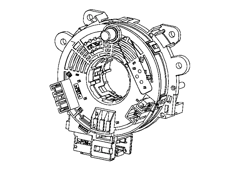
-
Steering switch signals pass through the combination switch (spiral cable) to the combination meter.
-
Combination meter sends the steering switch signals to the audio unit via AV communication.
-
Combination meter sends the speed signal to the audio unit via CAN communication.

-
Steering switches are connected to the combination meter through the combination switch (spiral cable).
-
Combination meter sends the steering switch signals to the audio unit via AV communication.
ANTENNA BASE
-
Antenna base is installed on the rear center of the roof.

-
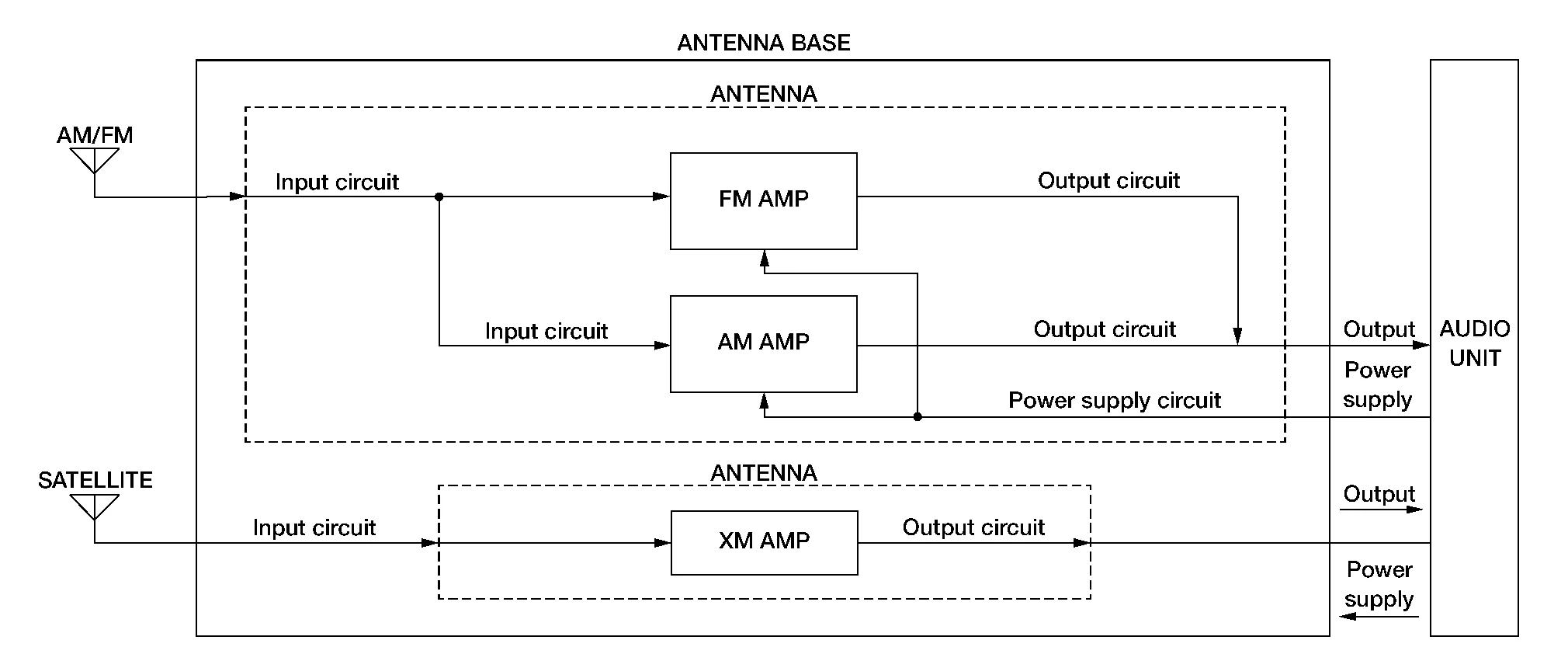
Antenna base incorporates the satellite antenna, AM/FM antenna and antenna amp.
-
Receives satellite radio waves and outputs them to audio unit.
-
Receives AM/FM radio waves and outputs them to audio unit.
ANTENNA SIGNAL PATH
-
AM/FM radio antenna located in the antenna base.
-
The AM/FM radio antenna has an antenna amp. to obtain sufficient reception power.
ANTENNA FEEDER LAYOUT
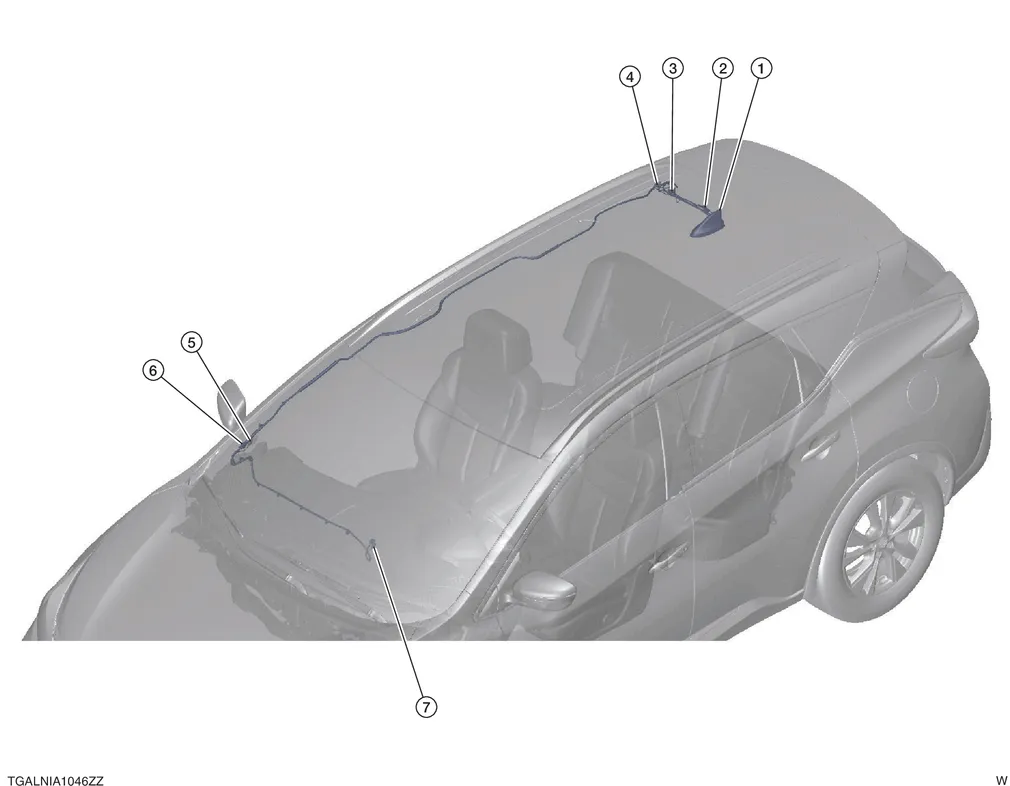
| 1. | Antenna base | 2. | R202, R203 | 3. | R102, R200 |
| 4. | R103, R201 | 5. | M99, R100 | 6. | M98, R101 |
| 7. | M124, M125 |

 System
System Description
SYSTEM DIAGRAMAudio Unit Input Signal (AV Communication)Transmit unitSignal name
Combination meter
Steering switch signal
Audio Unit Input Signal (CAN Communication)Transmit unitSignal name
BCM
Door switches state signal
Combination meter
Nissan Murano Vehicle speed signal
Hand brake switch signal
ECM
Engine RPM Signal
IPDM E/R
Battery voltage signal
AUDIO SYSTEMThe audio system consists of the following components:
Audio unit
Instrument panel tweeters
Front door speakers
Rear door speakers
Front auxiliary input jacks
Front auxiliary input jacks control unit
Microphone
Steering switches
Combination meter
Combination switch (spiral cable)
Accessory relay-2
Antenna base (AM/FM antenna, antenna amp...
Other information:
Nissan Murano (Z52) 2015-2024 Service Manual: U1010-49 Control Unit (can)
DTC Description DESCRIPTIONCAN controller controls the communication of ITS communication signal and the error detection.DTC DETECTION LOGIC DTC No. CONSULT screen terms (Trouble diagnosis content) DTC detection condition U1010-49 CONTROL UNIT (CAN) [Control unit (CAN)] Diagnosis condition When ignition switch is ON...
Nissan Murano (Z52) 2015-2024 Service Manual: B2578 in-Vehicle Sensor
DTC Description DTC DETECTION LOGICNOTE: If DTC is displayed along with DTC U1000, first perform the trouble diagnosis for DTC U1000. Refer to DTC Description. If DTC is displayed along with DTC U1010, first perform the trouble diagnosis for DTC U1010...
Categories
- Manuals Home
- Nissan Murano Owners Manual
- Nissan Murano Service Manual
- Shift lock release
- All-Wheel Drive (AWD) (if so equipped)
- Jacking up vehicle and removing the damaged tire
- New on site
- Most important about car
Autolight system
The autolight system allows the headlights to turn on and off automatically. The autolight system can:
Turn on the headlights, front parking, tail, license plate and instrument panel lights automatically when it is dark. Turn off all the lights (except daylight running lights) when it is light. Keep all the lights on for a period of time after you place the ignition switch in the OFF position and all doors are closed.