Nissan Murano: System Description / Diagnosis System (audio Unit)
The audio unit on board diagnosis performs the following functions listed in the table below:
| Mode | Description | |
|---|---|---|
| Self Diagnosis |
|
|
| Confirmation/Adjustment | Display Diagnosis |
The following check functions are available:
|
| Nissan Murano Vehicle Signals | Diagnosis of signals can be performed for Vehicle Speed, Ignition, Illumination Control, MR out, Illumination Switch, Reverse, Parking Brake and ACC. | |
| Navigation | Displayed, but not used. | |
| Error Location Display | The system malfunction and the frequency when occurring in the past are displayed. When the malfunctioning item is selected, the time that the selected malfunction last occurred is displayed. | |
| AV COMM Diagnosis | The AV communication condition of each unit of audio system can be monitored. | |
| Camera |
The following functions are available:
|
|
| Delete Unit Connection Log | Erase the connection history of unit. | |
| Initialize Settings | User Data Initialization is available. | |
| GPS Time Set | Displayed, but not used. | |
| Version Information | Version information of the Multi AV system is displayed. | |
| Software Update |
|
|
| ### Speaker Test | Individual speakers can be checked at the 100Hz and 4KHz range. | |
| Radio Tuner | FM Monitor and AM Monitor information can be observed. | |
| SXM | SXM Monitor information can be observed. | |
Perform CONSULT diagnosis if the audio unit on board diagnosis does not start, or the screen does not display anything.
METHOD OF STARTING
Audio Unit Self Diagnosis
-
Ignition switch ON.
-
Turn the audio system OFF.
-
While pressing the MENU button, turn the TUNE-SCROLL dial counterclockwise for 3 or more clicks, clockwise for 3 or more clicks, counterclockwise for 3 or more clicks. Shifting from current screen to previous screen is performed by pressing BACK button.
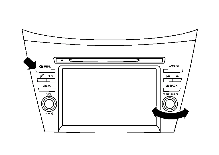
-
The trouble diagnosis initial screen is displayed, and “Self Diagnosis” and “Confirmation/Adjustment” can be selected.

SELF-DIAGNOSIS MODE
-
Start the self-diagnosis function and select “Self Diagnosis”.
-
Self-diagnosis subdivision screen is displayed, and the self-diagnosis mode starts.
-
The bar graph visible on the center of the self-diagnosis subdivision screen indicates progress of the trouble diagnosis.
-
-
Diagnosis results are displayed after the self-diagnosis is completed. The unit names and the connection lines are color-coded according to the diagnostic results.
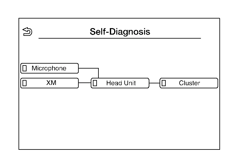
Diagnosis results Unit Connection line Normal Green Green Connection malfunction Gray Yellow Unit malfunction Note Red Green  NOTE:
NOTE:
Control Unit (audio unit) is displayed in red.
-
Replace audio unit if “Self-Diagnosis did not run because of a control unit malfunction” is indicated. The symptom is audio unit internal error. Refer to Removal and Installation.
-
If multiple errors occur at the same time for a single unit, the screen switch colors are determined according to the following order of priority: red > gray.
-
The comments of the self-diagnosis results can be viewed in the diagnosis result screen.
-
Detection Range of Self-diagnosis Mode
-
The self-diagnosis mode allows the technician to diagnose the connection in the communication line between audio unit and each unit and the internal operation of the audio unit.
-
Because the start condition of diagnosis function is a switch operation, the on board diagnosis function cannot be started up if any malfunction is detected in the audio unit switches.
SELF-DIAGNOSIS RESULTS
Only Unit Part Is Displayed In Red.
| Screen switch | Description | Possible malfunction location / Action to take |
|---|---|---|
| Head Unit | Malfunction is detected in audio unit power supply and ground circuits. |
Check audio unit power supply and ground circuits. Refer to Diagnosis Procedure. When no malfunction is detected in those circuits, replace audio unit. Refer to Removal and Installation. |
| XM | Malfunction is detected in satellite antenna signal circuit. |
Check satellite antenna signal circuit. Refer to DTC Diagnosis Procedure. When no malfunction is detected in the circuit, replace satellite antenna. Refer to Removal and Installation. |
| Microphone | Malfunction is detected in microphone signal circuit. |
Check microphone signal circuit. Refer to DTC Diagnosis Procedure. When no malfunction is detected in the circuit, replace microphone. Refer to Removal and Installation. |
| Cluster | Malfunction is detected in combination meter power supply and ground circuits. |
Check combination meter power supply and ground circuits. Refer to Diagnosis Procedure. When no malfunction is detected in those circuits, replace combination meter. Refer to Removal and Installation. |
A Connecting Cable Between Units Is Displayed In Yellow.
| Area with yellow connection lines | Description | Possible malfunction location / Action to take |
|---|---|---|
| Head Unit ⇔ XM | Satellite antenna connection malfunction detected. |
Satellite antenna disconnected. Refer to DTC Diagnosis Procedure. |
| Head Unit ⇔ Microphone | Microphone connection malfunction detected. |
Microphone disconnected. Refer to DTC Diagnosis Procedure. |
| Head unit ⇔ Cluster | AV communication circuits between audio unit and combination meter are malfunctioning. |
AV communication circuits between audio unit and combination meter. Refer to Diagnosis Procedure. |
CONFIRMATION/ADJUSTMENT MODE
-
Start the diagnosis function and select “Confirmation/Adjustment”. The confirmation/adjustment mode indicates where each item can be checked or adjusted.
-
Select each switch on the “Confirmation/Adjustment Mode” screen to display the relevant trouble diagnosis screen. Touch the “Back” to return to the initial Confirmation/Adjustment Mode screen.

Display Diagnosis
Confirmation of the audio unit screen operation.

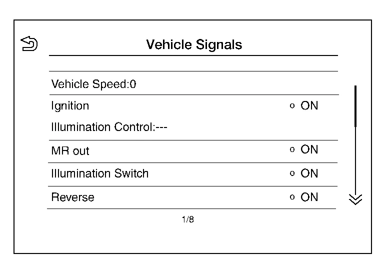
Vehicle Signals
A comparison check can be made of each actual vehicle signal and the signals recognized by the system.
Navigation
Displayed, but not used.

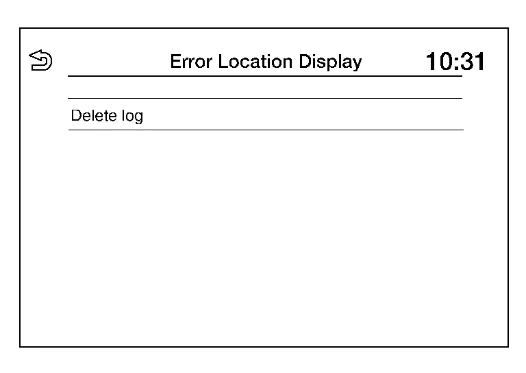
Error Location Display
Results of the error occurrence are represented by the time the error occurred.
AV COMM Diagnosis
AV COMM Monitor
-
Displays the communication status between audio unit (master unit) and each unit.
-
The error counter displays “OK” if any malfunction was not detected in the past and displays “0” if a malfunction is detected. It increases by 1 if the condition is normal at the next ignition switch ON cycle. The upper limit of the counter is 39.
-
The error counter is erased if “Reset” is pressed.

Camera
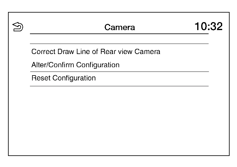
| Item | Description |
|---|---|
| Correct Draw Line of Rear view Camera | The guiding lines in the rear view monitor can be adjusted. |
| Alter/Confirm Configuration | Displays the current configuration data. |
| Reset Configuration | Initializes the camera system configuration. |
Delete Unit Connection Log
Deletes error records from the audio unit memory.

Initialize Settings
Initializes the audio unit memory.

GPS Time Set
Displayed, but not used.

Version Information
Version information of the components of the Multi AV system are displayed.

Software Update
Version of the audio unit software can be update.

### Speaker Test
Two test tones, 100Hz and 4KHz, can be generated to each speaker.

Radio Tuner
Displays FM and AM monitor information.

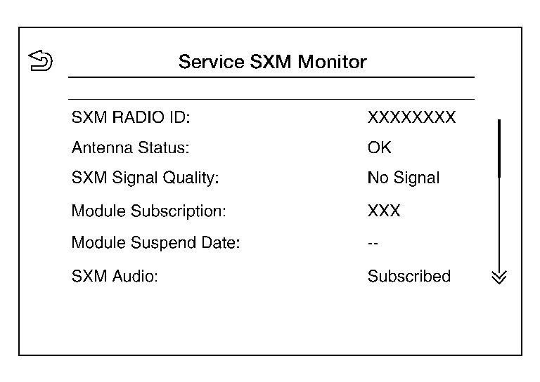
SXM
Displays SXM monitor information.
CONSULT FUNCTIONS
CONSULT performs the following functions via communication with the audio unit:
| Direct Diagnostic Mode | Description |
|---|---|
| ECU Identification | The audio unit part number is displayed. |
| Self Diagnostic Result | The audio unit self diagnostic results are displayed. |
| Data Monitor | The audio unit input/output data is displayed in real time. |
| Configuration |
|
| CAN Diag Support Mntr |
|
ECU IDENTIFICATION
The part number of audio unit is displayed.
SELF DIAGNOSTIC RESULT
Refer to DTC Index.
DATA MONITOR
NOTE:
The following table includes information (items) inapplicable to this Nissan Murano vehicle. For information (items) applicable to this vehicle, refer to CONSULT display items.
| Monitor Item [Unit] | Description |
|---|---|
| Sunload sensor [On/Off] | Indicates sunload sensor signal received from A/C auto amp. on CAN communication line. |
| Parking brake [On/Off] | Indicates condition of parking brake signal for the audio unit. |
| IGN SIG [On/Off] | Indicates condition of ignition signal. |
| Auto ACC [On/Off] | Indicates condition of auto ACC signal. |
| ACC [On/Off] | Indicates condition of ACC signal. |
| Aux IN 1 [Con/No con] | Indicates connection condition of Aux in jack. |
| Aux IN 2 [Con/No con] | Indicates connection condition of USB. |
| REV SIG [On/Off] | Indicates condition of reverse signal received from transmission range switch. |
| ILLUM SIG [On/Off] | Indicates condition of illumination signal for the audio unit. |
| Illumination Control [On/Off] | Indicates condition of illumination control signal for the audio unit. |
CONFIGURATION
Refer to Description.
CAN DIAG SUPPORT MNTR
Refer to CAN Diagnostic Support Monitor.
 System
System Description
SYSTEM DIAGRAMAudio Unit Input Signal (AV Communication)Transmit unitSignal name
Combination meter
Steering switch signal
Audio Unit Input Signal (CAN Communication)Transmit unitSignal name
BCM
Door switches state signal
Combination meter
Nissan Murano Vehicle speed signal
Hand brake switch signal
ECM
Engine RPM Signal
IPDM E/R
Battery voltage signal
AUDIO SYSTEMThe audio system consists of the following components:
Audio unit
Instrument panel tweeters
Front door speakers
Rear door speakers
Front auxiliary input jacks
Front auxiliary input jacks control unit
Microphone
Steering switches
Combination meter
Combination switch (spiral cable)
Accessory relay-2
Antenna base (AM/FM antenna, antenna amp...
 Ecu Diagnosis Information. Audio Unit
Values on the Diagnosis Tool
NOTE:
The following table includes information (items) inapplicable to this Nissan Murano vehicle. For information (items) applicable to this vehicle, refer to CONSULT display items...
Other information:
Nissan Murano (Z52) 2015-2024 Service Manual: B260a Ignition Relay
DTC Description DTC DETECTION LOGIC DTC No. CONSULT screen terms (Trouble diagnosis content) DTC Detection Condition B260A IGNITION RELAY (Ignition relay) Diagnosis condition When ignition switch ON. Signal (terminal) — Threshold — Diagnosis delay time 2 seconds or more POSSIBLE CAUSE Harness or connectors BCM IPDM E/R FAIL SAFE— DTC Confirmation Procedure PERFORM DTC CONFIRMATION PROCEDURE CONSULT Ignition switch ON under the following conditions and wait for at least 2 seconds: CVT selector lever is in the P (park) or N (neutral) position...
Nissan Murano (Z52) 2015-2024 Owners Manual: RCTA system operation
Side BSW/RCTA Indicator Light BSW/RCTA Indicator The RCTA system can help alert the driver of an approaching vehicle when the driver is backing out of a parking space. When the shift position is in R (Reverse) and the vehicle speed is less than approximately 5 mph (8 km/h), the RCTA system is operational...
Categories
- Manuals Home
- Nissan Murano Owners Manual
- Nissan Murano Service Manual
- Settings
- Tire rotation
- All-Wheel Drive (AWD) (if so equipped)
- New on site
- Most important about car
Luggage hooks

When securing items using luggage hooks located on the back of the seat or side finisher do not apply a load over more than 6.5 lbs. (29 N) to a single hook.
The luggage hooks that are located on the floor should have loads less than 110 lbs. (490 N) to a single hook.