Nissan Murano: System Description / System
-
The system switches fluid pressure of each brake caliper to increase, hold or decrease according to signals from control unit in ABS actuator and electric unit (control unit). This control system is applied to VDC function, TCS function, ABS function, EBD function, brake assist function, hill start assist function and automaticemergency braking function.
-
Fail-safe function is available for each function and is activated by each function when system malfunction occurs.
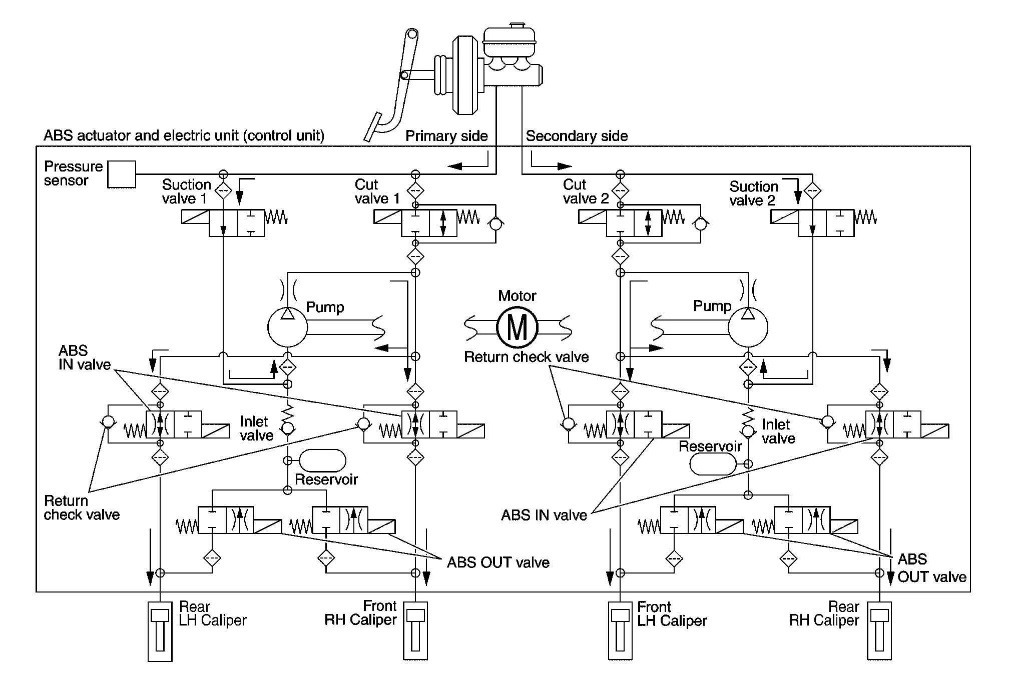
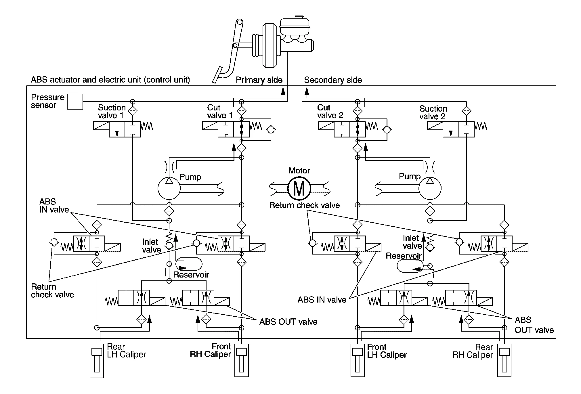
SYSTEM DIAGRAM

SIGNAL TRANSMISSION FUNCTION LIST
Major signal transmission between each unit via communication lines is shown in the following table:
| Component | Signal description |
|---|---|
| ECM |
Mainly transmits the following signals to ABS actuator and electric unit (control unit) via CAN communication:
Mainly receives the following signal from ABS actuator and electric unit (control unit) via CAN communication:
|
| TCM |
Mainly transmits the following signal to ABS actuator and electric unit (control unit) via CAN communication:
|
| Combination meter |
Mainly receives the following signals from ABS actuator and electric unit (control unit) via CAN communication:
Mainly receives the following signals from ABS actuator and electric unit (control unit) via CAN communication:
|
| Steering angle sensor |
Mainly transmits the following signals to ABS actuator and electric unit (control unit) via CAN communication:
|
VALVE OPERATION (VDC AND TCS FUNCTIONS)
The control unit built in the ABS actuator and electric unit (control unit) controls fluid pressure of the brake calipers by operating each valve.
VDC and TCS Functions are Operating (Pressure Increases)
| Name | Not activated | Pressure increases |
|---|---|---|
| Cut valve 1 | Power supply is not supplied (open) | Power supply is supplied (close) |
| Cut valve 2 | Power supply is not supplied (open) | Power supply is supplied (close) |
| Suction valve 1 | Power supply is not supplied (close) | Power supply is supplied (open) |
| Suction valve 2 | Power supply is not supplied (close) | Power supply is supplied (open) |
| ABS IN valve | Power supply is not supplied (open) | Power supply is not supplied (open) |
| ABS OUT valve | Power supply is not supplied (close) | Power supply is not supplied (close) |
| Each brake caliper (fluid pressure) | — | Pressure increases |
Front RH brake caliper
-
Brake fluid is conveyed to the pump from the master cylinder through suction valve 1 and is pressurized by the pump operation. The pressurized brake fluid is supplied to the front RH brake caliper through the ABS IN valve. For the left caliper, brake fluid pressure is maintained because the pressurization is unnecessary. The pressurization for the left caliper is controlled separately from the right caliper.
Front LH brake caliper
-
Brake fluid is conveyed to the pump from the master cylinder through suction valve 2 and is pressurized by the pump operation. The pressurized brake fluid is supplied to the front LH brake caliper through the ABS IN valve. For the right caliper, brake fluid pressure is maintained because the pressurization is unnecessary. The pressurization for the right caliper is controlled separately from the left caliper.
Rear RH brake caliper
-
Brake fluid is conveyed to the pump from the master cylinder through suction valve 2 and is pressurized by the pump operation. The pressurized brake fluid is supplied to the rear RH brake caliper through the ABS IN valve. For the left caliper, brake fluid pressure is maintained because the pressurization is unnecessary. The pressurization for the left caliper is controlled separately from the right caliper.
Rear LH brake caliper
-
Brake fluid is conveyed to the pump from the master cylinder through suction valve 1 and is pressurized by the pump operation. The pressurized brake fluid is supplied to the rear LH brake caliper through the ABS IN valve. For the right caliper, brake fluid pressure is maintained because the pressurization is unnecessary. The pressurization for the right caliper is controlled separately from the left caliper.
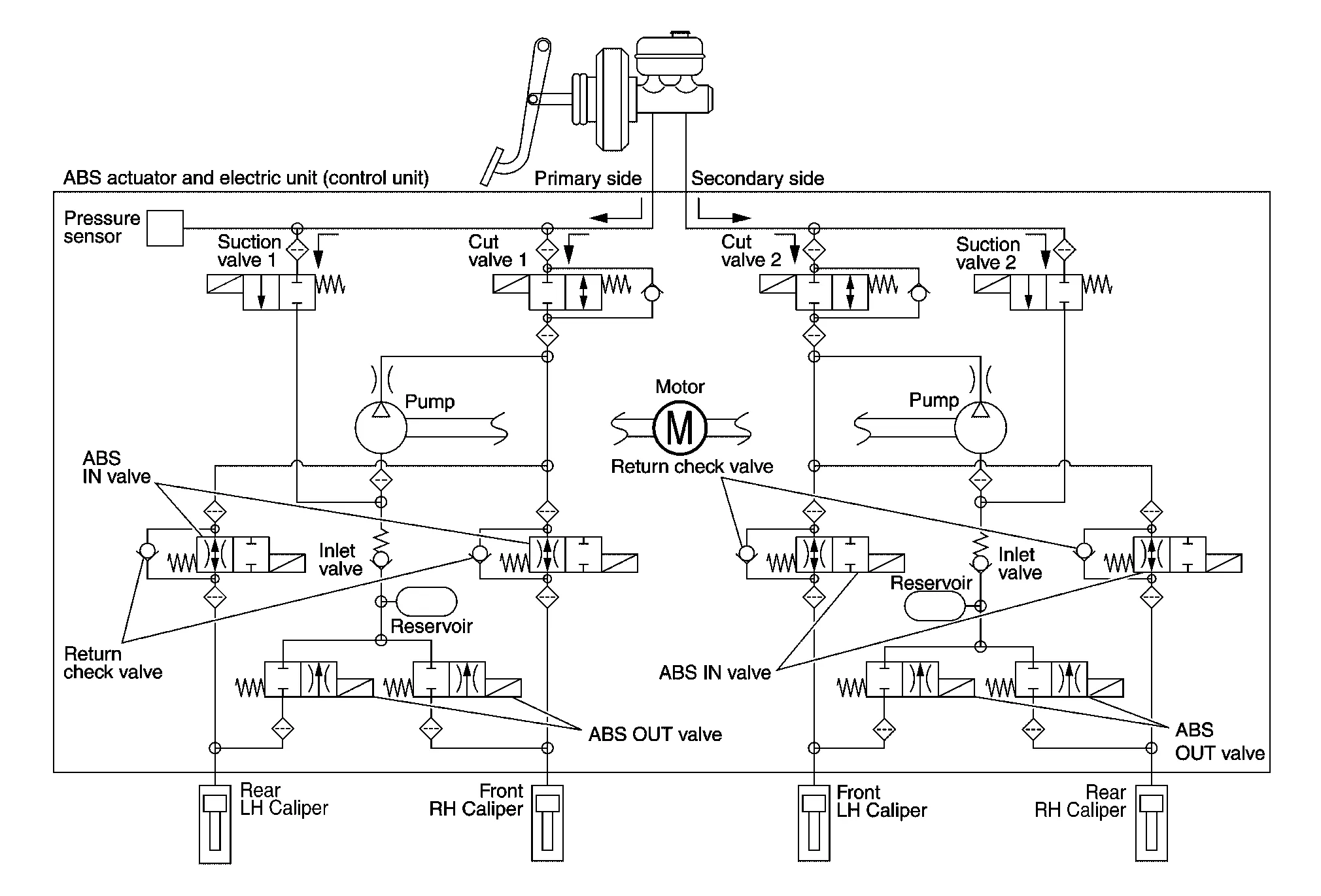
VDC and TCS Functions Start Operating (Pressure Holds)
| Name | Not activated | Pressure holds |
|---|---|---|
| Cut valve 1 | Power supply is not supplied (open) | Power supply is supplied (close) |
| Cut valve 2 | Power supply is not supplied (open) | Power supply is supplied (close) |
| Suction valve 1 | Power supply is not supplied (close) | Power supply is not supplied (close) |
| Suction valve 2 | Power supply is not supplied (close) | Power supply is not supplied (close) |
| ABS IN valve | Power supply is not supplied (open) | Power supply is not supplied (open) |
| ABS OUT valve | Power supply is not supplied (close) | Power supply is not supplied (close) |
| Each brake caliper (fluid pressure) | — | Pressure holds |
Front RH brake caliper
-
Since the cut valve 1 and the suction valve 1 are closed, the front RH brake caliper, master cylinder, and reservoir are blocked. This maintains fluid pressure applied on the front RH brake caliper. The pressurization for the left caliper is controlled separately from the right caliper.
Front LH brake caliper
-
Since the cut valve 2 and the suction valve 2 are closed, the front LH brake caliper, master cylinder, and reservoir are blocked. This maintains fluid pressure applied on the front LH brake caliper. The pressurization for the right caliper is controlled separately from the left caliper.
Rear RH brake caliper
-
Since the cut valve 2 and the suction valve 2 are closed, the rear RH brake caliper, master cylinder, and reservoir are blocked. This maintains fluid pressure applied on the rear RH brake caliper. The pressurization for the left caliper is controlled separately from the right caliper.
Rear LH brake caliper
-
Since the cut valve 1 and the suction valve 1 are closed, the rear LH brake caliper, master cylinder, and reservoir are blocked. This maintains fluid pressure applied on the rear LH brake caliper. The pressurization for the right caliper is controlled separately from the left caliper.
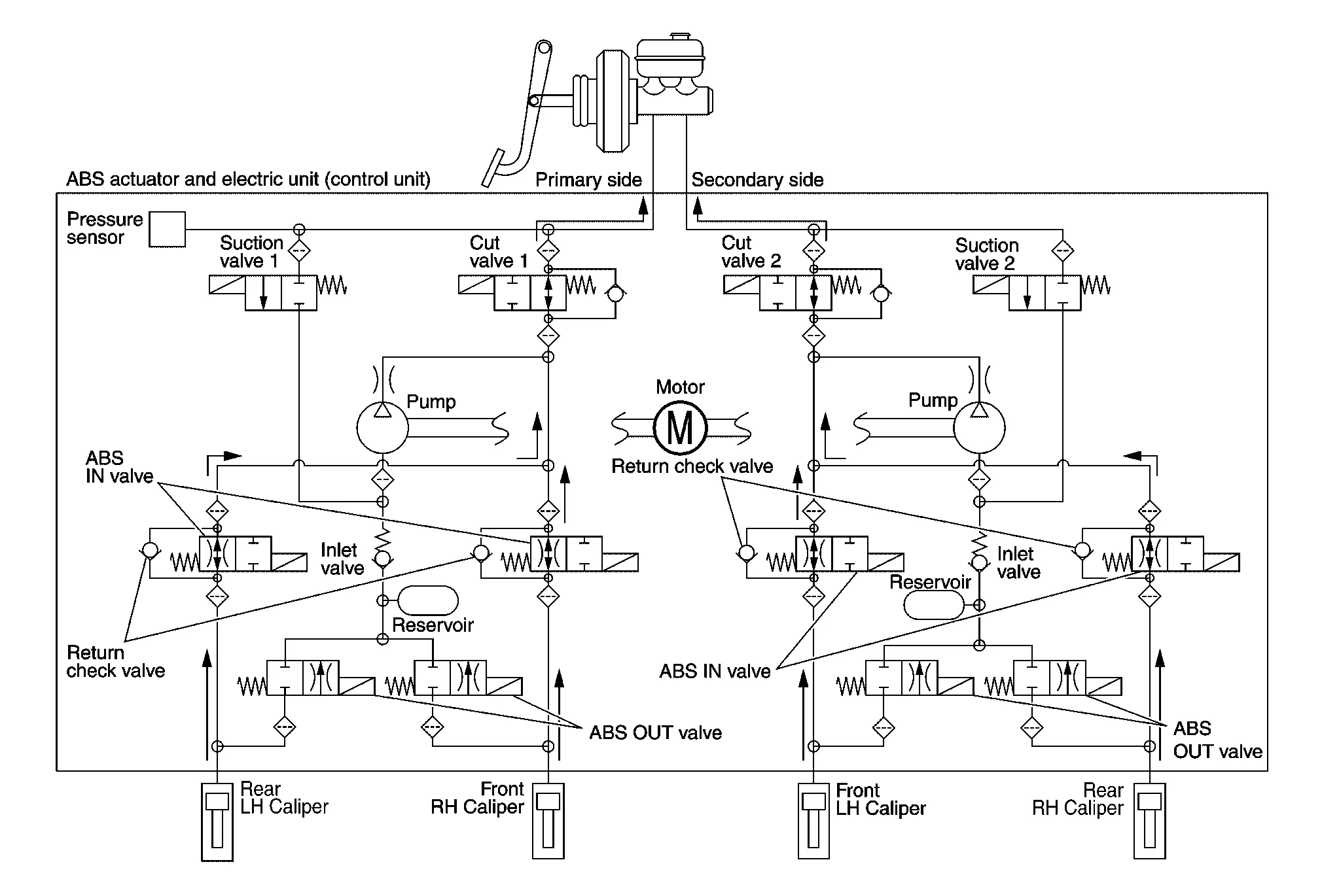
VDC and TCS Functions Operating (Pressure Decreases)
| Name | Not activated | During pressure decreases |
|---|---|---|
| Cut valve 1 | Power supply is not supplied (open) | Power supply is not supplied (open) |
| Cut valve 2 | Power supply is not supplied (open) | Power supply is not supplied (open) |
| Suction valve 1 | Power supply is not supplied (close) | Power supply is not supplied (close) |
| Suction valve 2 | Power supply is not supplied (close) | Power supply is not supplied (close) |
| ABS IN valve | Power supply is not supplied (open) | Power supply is not supplied (open) |
| ABS OUT valve | Power supply is not supplied (close) | Power supply is not supplied (close) |
| Each brake caliper (fluid pressure) | — | Pressure decreases |
Front RH brake caliper
-
Since the suction valve 1 and the ABS OUT valve are closed and the cut valve 1 and the ABS IN valve are open, the fluid pressure applied on the front RH brake caliper is reduced by supplying the fluid pressure to the master cylinder via the ABS IN valve and the cut valve 1. The pressurization for the right caliper is controlled separately from the left caliper.
Front LH brake caliper
-
Since the suction valve 2 and the ABS OUT valve are closed and the cut valve 2 and the ABS IN valve are open, the fluid pressure applied on the front LH brake caliper is reduced by supplying the fluid pressure to the master cylinder via the ABS IN valve and the cut valve 2. The pressurization for the left caliper is controlled separately from the right caliper.
Rear RH brake caliper
-
Since the suction valve 2 and the ABS OUT valve are closed and the cut valve 2 and the ABS IN valve are open, the fluid pressure applied on the rear RH brake caliper is reduced by supplying the fluid pressure to the master cylinder via the ABS IN valve and the cut valve 2. The pressurization for the right caliper is controlled separately from the left caliper.
Rear LH brake caliper
-
Since the suction valve 1 and the ABS OUT valve are closed and the cut valve 1 and the ABS IN valve are open, the fluid pressure applied on the rear LH brake caliper is reduced by supplying the fluid pressure to the master cylinder via the ABS IN valve and the cut valve 1. The pressurization for the left caliper is controlled separately from the right caliper.
Component Parts and Function
| Component | Function |
|---|---|
| Pump | Returns the brake fluid reserved in reservoir to master cylinder by reducing pressure. |
| Motor | Activates the pump according to signals from ABS actuator and electric unit (control unit). |
|
Cut valve 1 Cut valve 2 |
Shuts off the ordinary brake line from master cylinder. |
|
Suction valve 1 Suction valve 2 |
Supplies the brake fluid from master cylinder to the pump. |
| ABS IN valve | Switches the fluid pressure line to increase or hold according to signals from control unit. |
| ABS OUT valve | Switches the fluid pressure line to increase, hold or decrease according to signals from control unit. |
| Return check valve | Returns the brake fluid from brake caliper to master cylinder by bypassing orifice of each valve when brake is released. |
| Reservoir | Temporarily reserves the brake fluid drained from brake caliper, so that pressure efficiently decreases when decreasing pressure of brake caliper. |
| Pressure sensor | Detects the brake fluid pressure and transmits signal to ABS actuator and electric unit (control unit). |
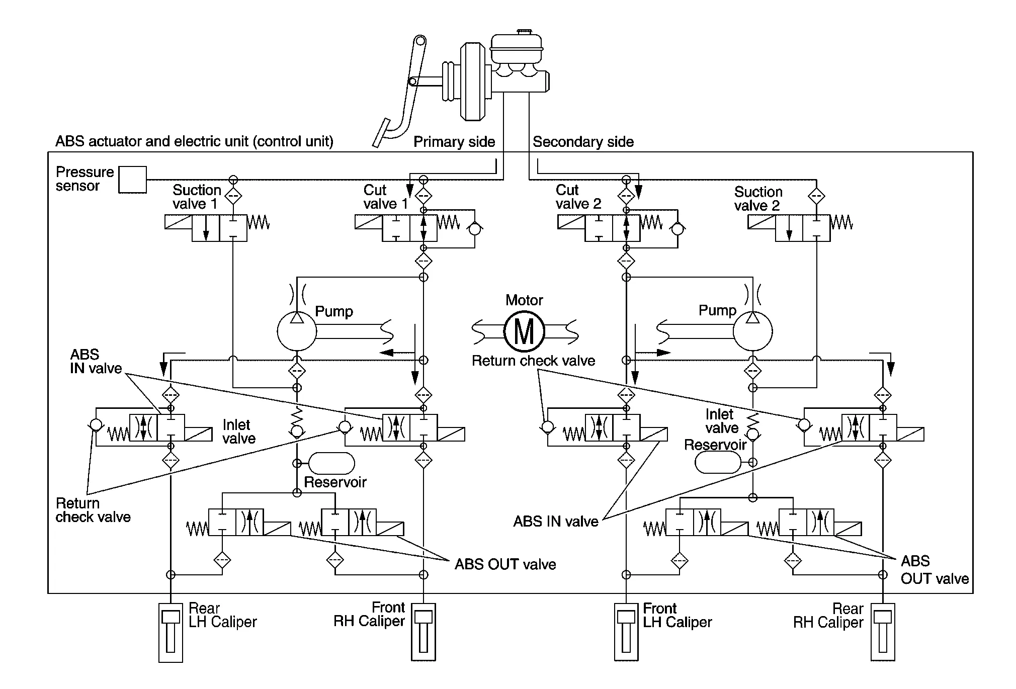
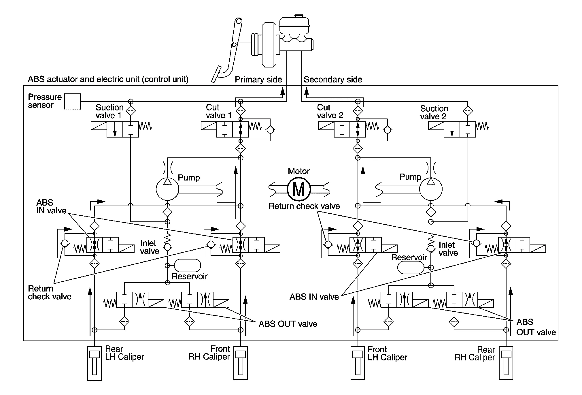
VALVE OPERATION (ABS AND EBD FUNCTIONS)
The control unit built into the ABS actuator and electric unit (control unit) controls fluid pressure of the brake calipers by operating each valve.
Brake Pedal Applied or ABS Function Operating (Pressure Increases)

| Name | Not activated | During pressure increases |
|---|---|---|
| Cut valve 1 | Power supply is not supplied (open) | Power supply is not supplied (open) |
| Cut valve 2 | Power supply is not supplied (open) | Power supply is not supplied (open) |
| Suction valve 1 | Power supply is not supplied (close) | Power supply is not supplied (close) |
| Suction valve 2 | Power supply is not supplied (close) | Power supply is not supplied (close) |
| ABS IN valve | Power supply is not supplied (open) | Power supply is not supplied (open) |
| ABS OUT valve | Power supply is not supplied (close) | Power supply is not supplied (close) |
| Each brake caliper (fluid pressure) | — | Pressure increases |
Front RH brake caliper
-
When the cut valve 1 and the ABS IN valve opens, brake fluid is supplied to the front RH brake caliper from the master cylinder through the ABS IN valve. Brake fluid does not flow into the reservoir because the ABS OUT valve is closed.
Front LH brake caliper
-
When the cut valve 2 and the ABS IN valve opens, brake fluid is supplied to the front LH brake caliper from the master cylinder through the ABS IN valve. Brake fluid does not flow into the reservoir because the ABS OUT valve is closed.
Rear RH brake caliper
-
When the cut valve 2 and the ABS IN valve opens, brake fluid is supplied to the rear RH brake caliper from the master cylinder through the ABS IN valve. Brake fluid does not flow into the reservoir because the ABS OUT valve is closed.
Rear LH brake caliper
-
When the cut valve 1 and the ABS IN valve opens, brake fluid is supplied to the rear LH brake caliper from the master cylinder through the ABS IN valve. Brake fluid does not flow into the reservoir because the ABS OUT valve is closed.
ABS Function Starts Operating (Pressure Holds)
| Name | Not activated | During pressure holds |
|---|---|---|
| Cut valve 1 | Power supply is not supplied (open) | Power supply is not supplied (open) |
| Cut valve 2 | Power supply is not supplied (open) | Power supply is not supplied (open) |
| Suction valve 1 | Power supply is not supplied (close) | Power supply is not supplied (close) |
| Suction valve 2 | Power supply is not supplied (close) | Power supply is not supplied (close) |
| ABS IN valve | Power supply is not supplied (open) | Power supply is supplied (close) |
| ABS OUT valve | Power supply is not supplied (close) | Power supply is not supplied (close) |
| Each brake caliper (fluid pressure) | — | Pressure holds |
Front RH brake caliper
-
Since the ABS IN valve and the ABS OUT valve are closed, the front RH brake caliper, master cylinder, and reservoir are blocked. This maintains fluid pressure applied on the front RH brake caliper.
Front LH brake caliper
-
Since the ABS IN valve and the ABS OUT valve are closed, the front LH brake caliper, master cylinder, and reservoir are blocked. This maintains fluid pressure applied on the front LH brake caliper.
Rear RH brake caliper
-
Since the ABS IN valve and the ABS OUT valve are closed, the rear RH brake caliper, master cylinder, and reservoir are blocked. This maintains fluid pressure applied on the rear RH brake caliper.
Rear LH brake caliper
-
Since the ABS IN valve and the ABS OUT valve are closed, the rear LH brake caliper, master cylinder, and reservoir are blocked. This maintains fluid pressure applied on the rear LH brake caliper.
ABS Function Operating (Pressure Decreases)
| Name | Not activated | During pressure decreases |
|---|---|---|
| Cut valve 1 | Power supply is not supplied (open) | Power supply is not supplied (open) |
| Cut valve 2 | Power supply is not supplied (open) | Power supply is not supplied (open) |
| Suction valve 1 | Power supply is not supplied (close) | Power supply is not supplied (close) |
| Suction valve 2 | Power supply is not supplied (close) | Power supply is not supplied (close) |
| ABS IN valve | Power supply is not supplied (open) | Power supply is supplied (close) |
| ABS OUT valve | Power supply is not supplied (close) | Power supply is supplied (open) |
| Each brake caliper (fluid pressure) | — | Pressure decreases |
Front RH brake caliper
-
Since the ABS IN valve is closed and the ABS OUT valve is opened, fluid pressure applied on the front RH brake caliper is supplied to the reservoir through the ABS OUT valve. This fluid pressure decreases when sent to the master cylinder by the pump.
Front LH brake caliper
-
Since the ABS IN valve is closed and the ABS OUT valve is opened, fluid pressure applied on the front LH brake caliper is supplied to the reservoir through the ABS OUT valve. This fluid pressure decreases when sent to the master cylinder by the pump.
Rear RH brake caliper
-
Since the ABS IN valve is closed and the ABS OUT valve is opened, fluid pressure applied on the rear RH brake caliper is supplied to the reservoir through the ABS OUT valve. This fluid pressure decreases when sent to the master cylinder by the pump.
Rear LH brake caliper
-
Since the ABS IN valve is closed and the ABS OUT valve is opened, fluid pressure applied on the rear LH brake caliper is supplied to the reservoir through the ABS OUT valve. This fluid pressure decreases when sent to the master cylinder by the pump.
ABS Function Operating (Pressure Increases)
| Name | Not activated | During pressure increases |
|---|---|---|
| Cut valve 1 | Power supply is not supplied (open) | Power supply is not supplied (open) |
| Cut valve 2 | Power supply is not supplied (open) | Power supply is not supplied (open) |
| Suction valve 1 | Power supply is not supplied (close) | Power supply is not supplied (close) |
| Suction valve 2 | Power supply is not supplied (close) | Power supply is not supplied (close) |
| ABS IN valve | Power supply is not supplied (open) | Power supply is not supplied (open) |
| ABS OUT valve | Power supply is not supplied (close) | Power supply is not supplied (close) |
| Each brake caliper (fluid pressure) | — | Pressure increases |
Front RH brake caliper
-
Brake fluid is supplied to the front RH brake caliper from the master cylinder through the cut valve 1 and the ABS IN valve. Since the suction valve 1 and the ABS OUT valve is closed, the fluid does not flow into the reservoir. The amount of brake fluid supplied to the front RH brake caliper from the master cylinder is controlled according to time that the ABS IN valve is not energized (time that the ABS IN valve is open).
Front LH brake caliper
-
Brake fluid is supplied to the front LH brake caliper from the master cylinder through the cut valve 2 and the ABS IN valve. Since the suction valve 2 and the ABS OUT valve is closed, the fluid does not flow into the reservoir. The amount of brake fluid supplied to the front LH brake caliper from the master cylinder is controlled according to time that the ABS IN valve is not energized (time that the ABS IN valve is open).
Rear RH brake caliper
-
Brake fluid is supplied to the rear RH brake caliper from the master cylinder through the cut valve 2 and the ABS IN valve. Since the suction valve 2 and the ABS OUT valve is closed, the fluid does not flow into the reservoir. The amount of brake fluid supplied to the rear RH brake caliper from the master cylinder is controlled according to time that the ABS IN valve is not energized (time that the ABS IN valve is open).
Rear LH brake caliper
-
Brake fluid is supplied to the rear LH brake caliper from the master cylinder through the cut valve 1 and the ABS IN valve. Since the suction valve 1 and the ABS OUT valve is closed, the fluid does not flow into the reservoir. The amount of brake fluid supplied to the rear LH brake caliper from the master cylinder is controlled according to time that the ABS IN valve is not energized (time that the ABS IN valve is open).
Brake Release
| Name | Not activated | During brake release |
|---|---|---|
| Cut valve 1 | Power supply is not supplied (open) | Power supply is not supplied (open) |
| Cut valve 2 | Power supply is not supplied (open) | Power supply is not supplied (open) |
| Suction valve 1 | Power supply is not supplied (close) | Power supply is not supplied (close) |
| Suction valve 2 | Power supply is not supplied (close) | Power supply is not supplied (close) |
| ABS IN valve | Power supply is not supplied (open) | Power supply is not supplied (open) |
| ABS OUT valve | Power supply is not supplied (close) | Power supply is not supplied (close) |
| Each brake caliper (fluid pressure) | — | Pressure decreases |
Front RH brake caliper
-
Brake fluid is supplied to the front RH brake caliper through the return check valve of the ABS IN valve and the cut valve 1, and returns to the master cylinder.
Front LH brake caliper
-
Brake fluid is supplied to the front LH brake caliper through the return check valve of the ABS IN valve and the cut valve 2, and returns to the master cylinder.
Rear RH brake caliper
-
Brake fluid is supplied to the rear RH brake caliper through the return check valve of the ABS IN valve and the cut valve 2, and returns to the master cylinder.
Rear LH brake caliper
-
Brake fluid is supplied to the rear LH brake caliper through the return check valve of the ABS IN valve and the cut valve 1, and returns to the master cylinder.
Component Parts and Function
| Component | Function |
|---|---|
| Pump | Returns the brake fluid reserved in reservoir to master cylinder by reducing pressure. |
| Motor | Activates the pump according to signals from ABS actuator and electric unit (control unit). |
|
Cut valve 1 Cut valve 2 |
Shuts off the ordinary brake line from master cylinder. |
|
Suction valve 1 Suction valve 2 |
Supplies the brake fluid from master cylinder to the pump. |
| ABS IN valve | Switches the fluid pressure line to increase or hold according to signals from control unit. |
| ABS OUT valve | Switches the fluid pressure line to increase, hold or decrease according to signals from control unit. |
| Return check valve | Returns the brake fluid from brake caliper to master cylinder by bypassing orifice of each valve when brake is released. |
| Reservoir | Temporarily reserves the brake fluid drained from brake caliper, so that pressure efficiently decreases when decreasing pressure of brake caliper. |
| Pressure sensor | Detects the brake fluid pressure and transmits signal to ABS actuator and electric unit (control unit). |
CONDITIONS FOR WARNING LAMP ILLUMINATION
Turns ON when ignition switch ON and OFF when the system is normal for bulb check purposes.
| Condition (status) | ABS warning lamp | Brake warning lamp | AEB warning lamp | VDC warning lamp |
|---|---|---|---|---|
| Ignition switch OFF | OFF | OFF | OFF | OFF |
| For approx. 1 second after the ignition switch ON | ON | ON | ON | ON |
| Approx. 2 seconds after ignition switch ON (when the system is in normal operation) | OFF | OFF | OFF | OFF |
| After engine starts | OFF | OFF | OFF | OFF |
| When brake fluid is less than the specified level (brake fluid level switch ON) | OFF | ON | OFF | OFF |
| When parking brake operates (parking brake switch ON) | OFF | ON | OFF | OFF |
| VDC function is malfunctioning | OFF | OFF | OFF | ON |
| TCS function is malfunctioning | OFF | OFF | OFF | ON |
| ABS function is malfunctioning | ON | OFF | OFF | ON |
| EBD function is malfunctioning | ON | ON | OFF | ON |
| AEB function is malfunctioning | OFF | OFF | ON | OFF |
| Brake assist function is malfunctioning | OFF | OFF | OFF | ON |
| Hill start assist function is malfunctioning | OFF | OFF | OFF | ON |
| Brake force distribution function is malfunctioning | OFF | OFF | OFF | ON |
| When brake booster vacuum decreases | OFF | ON | OFF | OFF |
| When vacuum sensor is malfunctioning | OFF | ON | OFF | OFF |
| VDC function is operating | OFF | OFF | OFF | Blinking |
| TCS function is operating | OFF | OFF | OFF | Blinking |
| ABS function is operating | OFF | OFF | OFF | OFF |
| EBD function is operating | OFF | OFF | OFF | OFF |
| AEB function is operating | OFF | OFF | Blinking | OFF |
| Brake assist function is operating | OFF | OFF | OFF | OFF |
| Hill start assist function is operating | OFF | OFF | OFF | OFF |
CONDITIONS FOR INDICATOR LAMP ILLUMINATION
VDC OFF indicator lamp
-
Turns ON when VDC function and TCS function are switched to non-operational status (OFF) by VDC OFF switch.
-
Turns ON when ignition switch ON and OFF when the system is normal for bulb check purposes.
| Condition (status) | VDC OFF indicator lamp |
|---|---|
| Ignition switch OFF | OFF |
| For approx. 1 second after the ignition switch ON | ON |
| Approx. 1 second after ignition switch ON (when the system is in normal operation). | OFF |
| When VDC OFF switch is ON (VDC function TCS function are OFF) | ON |
- Vdc Function
- Tcs Function
- Abs Function
- Ebd Function
- Brake Assist Function
- Hill Start Assist Function
- Warning/indicator/chime List
 Component Parts. Brake Control System
Component Parts Location
A.
Steering column
(view with steering wheel removed)
B.
Engine room (LH)
C.
Engine room (LH)
D.
Engine room (RH)
E...
 Vdc Function
System Description
SYSTEM DIAGRAM
Side slip or tail slip may occur while driving on a slippery road or intending urgent evasive driving. VDC function detects side slip status using each sensor when side slip or tail slip is about to occur and improves Nissan Murano vehicle stability by brake control and engine output control during driving...
Other information:
Nissan Murano (Z52) 2015-2024 Owners Manual: Hitch ball
Choose a hitch ball of the proper size and weight rating for your trailer: The required hitch ball size is stamped on most trailer couplers. Most hitch balls also have the size printed on the top of the ball. Choose the proper class hitch ball based on the trailer weight...
Nissan Murano (Z52) 2015-2024 Service Manual: Tire Size Incorrect Is Displayed on Information Display
Diagnosis Procedure While driving, AWD warning icon/display (Tire Size Incorrect: See Owner′s Manual) is displayed on information display.CHECK TIRE Check the following: Tire pressure Wear condition Front and rear tire size (There is no difference between front and rear tires...
Categories
- Manuals Home
- Nissan Murano Owners Manual
- Nissan Murano Service Manual
- High Beam Assist (if so equipped)
- Intelligent Forward Collision Warning (I-FCW)
- System malfunction
- New on site
- Most important about car
Luggage hooks

When securing items using luggage hooks located on the back of the seat or side finisher do not apply a load over more than 6.5 lbs. (29 N) to a single hook.
The luggage hooks that are located on the floor should have loads less than 110 lbs. (490 N) to a single hook.