Nissan Murano: System / Vdc Function
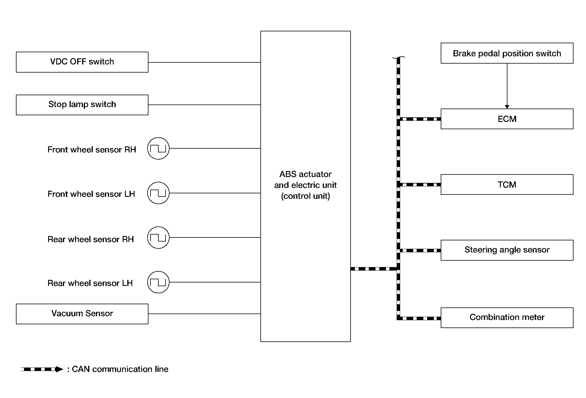
SYSTEM DIAGRAM
-
Side slip or tail slip may occur while driving on a slippery road or intending urgent evasive driving. VDC function detects side slip status using each sensor when side slip or tail slip is about to occur and improves Nissan Murano vehicle stability by brake control and engine output control during driving.
-
In addition to ABS function, EBD function and TCS function, target side slip amount is calculated according to steering operation amount from steering angle sensor and brake operation amount from brake pressure sensor. By comparing this information with Nissan Murano vehicle side slip amount that is calculated from information from yaw rate/side/decel G sensor and wheel sensor, Nissan Murano vehicle driving conditions (conditions of understeer or oversteer) are judged and vehicle stability is improved by brake force control on all wheels and engine output control.

-
VDC function can be switched to non-operational status (OFF) by operating VDC OFF switch. In this case, VDC OFF indicator lamp turns ON.
-
Control unit portion automatically improves driving stability by performing brake force control as well as engine output control, by transmitting drive signal to actuator portion according to difference between target side slip amount and Nissan Murano vehicle side slip amount
-
VDC warning lamp blinks while VDC function is in operation and indicates to the driver that the function is in operation.
-
CONSULT can be used to diagnose the system diagnosis.
-
Fail-safe function is adopted. When a malfunction occurs in VDC function, the control is suspended for VDC function, TCS function, brake assist function, hill start assist function and brake force distribution function. The Nissan Murano vehicle status becomes the same as models without VDC function, TCS function, brake assist function and hill start assist function. However, ABS function and EBD function are operated normally. Refer to Fail-Safe.
SIGNAL TRANSMISSION FUNCTION LIST
Major signal transmission between each unit via communication lines is shown in the following table:
| Component | Signal description |
|---|---|
| ECM |
Mainly transmits the following signals to ABS actuator and electric unit (control unit) via CAN communication:
Mainly receives the following signal from ABS actuator and electric unit (control unit) via CAN communication:
|
| TCM |
Mainly transmits the following signal to ABS actuator and electric unit (control unit) via CAN communication:
|
| Combination meter |
Mainly receives the following signals from ABS actuator and electric unit (control unit) via CAN communication:
Mainly receives the following signals from ABS actuator and electric unit (control unit) via CAN communication:
|
| Steering angle sensor |
Mainly transmits the following signals to ABS actuator and electric unit (control unit) via CAN communication:
|
OPERATION CHARACTERISTICS
VDC Function That Prevents Oversteer Tendency
-
During cornering, brake force (brake fluid pressure) is applied on front wheel and rear wheel on the outer side of turn. Momentum directing towards the outer side of turn is generated. Oversteer is prevented.

-
Changing driving lane on a slippery road when oversteer tendency is judged large, engine output is controlled as well as brake force (brake fluid pressure) of 4 wheels. Oversteer tendency decreases.

VDC Function That Prevents Understeer Tendency
-
During cornering, brake force (brake fluid pressure) is applied on front wheel and rear wheel on the inner side of turn. Momentum directing towards the inner side of turn is generated. Understeer is prevented.

-
Applying braking during cornering on a slippery road when understeer tendency is judged large, engine output is controlled as well as brake force (brake fluid pressure) of four wheels. Understeer tendency decreases.

 System
System Description
The system switches fluid pressure of each brake caliper to increase, hold or decrease according to signals from control unit in ABS actuator and electric unit (control unit)...
 Tcs Function
System Description
SYSTEM DIAGRAM
Wheel spin status of drive wheel is detected by wheel sensor of 4 wheels. Engine output and transmission shift status are controlled so that slip rate of drive wheels is in appropriate level...
Other information:
Nissan Murano (Z52) 2015-2024 Owners Manual: Exterior and interior lights
* It is recommended that you visit a NISSAN dealer for replacement. Always check with the Parts Department at a NISSAN dealer for the latest parts information. Map light Headlight assembly Personal light Door mirror turn signal light Fog light (if so equipped) High-mounted stop light License plate light Backup (reversing) light assembly Rear combination light Cargo light Daytime running light Replacement procedures All other lights are either type A, B, C or D...
Nissan Murano (Z52) 2015-2024 Service Manual: Power Supply and Ground Circuit
Diagnosis Procedure CHECK FUSIBLE LINKS Check that the following fusible links are not blown: Terminal Signal name Fusible link No. Capacity 1 Battery power supply E 80 A 2 A 250 A C 80 A 3 A 250 A B 100 A N 40 A Is the fusible link blown? YES>> Replace the blown fusible link after repairing the affected circuit...
Categories
- Manuals Home
- Nissan Murano Owners Manual
- Nissan Murano Service Manual
- Checking engine oil level
- Warning lights
- Intelligent Forward Collision Warning (I-FCW)
- New on site
- Most important about car
Fuel gauge

The gauge indicates the approximate fuel level in the tank.
The gauge may move slightly during braking, turning, acceleration, or going up or down hills.
The gauge needle returns to 0 (Empty) after the ignition switch is placed in the OFF position.