
Nissan Murano: Starting and driving / Intelligent Forward Collision Warning (I-FCW)
WARNING
Failure to follow the warnings and instructions for proper use of the I-FCW system could result in serious injury or death.
- The I-FCW system can help warn the driver before a collision occurs but will not avoid a collision. It is the driver’s responsibility to stay alert, drive safely and be in control of the vehicle at all times.
The I-FCW system can help alert the driver whenthere is a sudden braking of a second vehicle traveling in front of the vehicle ahead in the same lane.
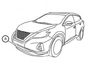
The I-FCW system uses a radar sensor A located on the front of the vehicle to measure the distance to the vehicle ahead in the same lane.
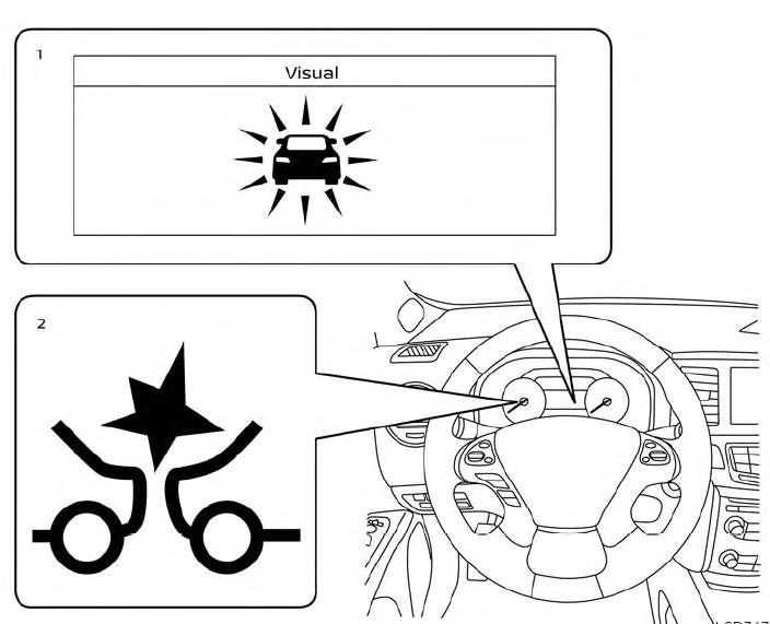
- Vehicle ahead detection indicator
- AEB system warning light
- I-FCW system operation
- Turning the I-FCW system on/off
- I-FCW system limitations
- System temporarily unavailable
- System malfunction
- System maintenance
 System maintenance
The radar sensor is located on the front of
the vehicle . The camera is located
on
the upper side of the windshield .
To keep the AEB with Pedestrian Detection
system operating properly, be sure to observe
the following:
Always keep the sensor areas of the
front bumper and windshield clean...
 I-FCW system operation
The I-FCW system operates at speeds
above approximately 3 mph (5 km/h).
If there is a potential risk of a forward collision,
the I-FCW system will warn the driver
by blinking the vehicle ahead detection indicator,
and sounding an audible alert...
Other information:
Nissan Murano (Z52) 2015-2024 Service Manual: C1b55-00 Radar Blockage
DTC Description DTC DETECTION LOGIC DTC No. CONSULT screen terms (Trouble diagnosis content) DTC detection condition C1B55-00 RADAR BLOCKAGE (Radar blockage) Diagnosis condition When ignition switch is ON. Signal (terminal) – Threshold Side radar is blocked Diagnosis delay time – NOTE: DTC “C1B55-00” may be detected under the following conditions except for possible cause...
Nissan Murano (Z52) 2015-2024 Service Manual: Engine Control System Symptoms
Symptom Table SYSTEM — BASIC ENGINE CONTROL SYSTEM SYMPTOM Reference page HARD/NO START/RESTART (EXCP. HA) ENGINE STALL HESITATION/SURGING/FLAT SPOT SPARK KNOCK/DETONATION LACK OF POWER/POOR ACCELERATION HIGH IDLE/LOW IDLE ROUGH IDLE/HUNTING IDLING VIBRATION SLOW/NO RETURN TO IDLE OVERHEATS/WATER TEMPERATURE HIGH EXCESSIVE FUEL CONSUMPTION EXCESSIVE OIL CONSUMPTION BATTERY DEAD (UNDER CHARGE) Warranty symptom code AA AB AC AD AE AF AG AH AJ AK AL AM HA Fuel Fuel pump circuit 1 1 2 3 2 2 2 3 2 Diagnosis Procedure Fuel pressure regulator system 3 3 4 4 4 4 4 4 4 4 Work Procedure Fuel injector circuit 1 1 2 3 2 2 2 2 Component Function Check Evaporative emission system 3 3 4 4 4 4 4 4 4 4 System Description Air Positive crankcase ventilation system 3 3 4 4 4 4 4 4 4 4 1 Positive Crankcase Ventilation (PCV) Incorrect idle speed adjustment 1 1 1 1 1 Work Procedure Electric throttle control actuator 1 1 2 3 3 2 2 2 2 2 2 DTC Description, DTC Description Ignition Incorrect ignition timing adjustment 3 3 1 1 1 1 1 1 Work Procedure Ignition circuit 1 1 2 2 2 2 2 2 Component Function Check Power supply and ground circuit 2 2 3 3 3 3 3 2 3 Diagnosis Procedure Mass air flow sensor circuit 1 1 2 2 2 2 2 2 DTC Description, DTC Description Engine coolant temperature sensor circuit 3 3 3 DTC Description, DTC Description Air fuel ratio (A/F) sensor 1 circuit DTC Description, DTC Description, DTC Description, DTC Description, DTC Description Throttle position sensor circuit 2 2 DTC Description, DTC Description, DTC Description, DTC Description, DTC Description Accelerator pedal position sensor circuit 3 2 1 DTC Description, DTC Description, DTC Description, DTC Description Knock sensor circuit 2 3 DTC Description Engine oil temperature sensor 4 2 3 DTC Description, DTC Description Crankshaft position sensor (POS) circuit 2 2 DTC Description Camshaft position sensor (PHASE) circuit 3 2 DTC Description Nissan Murano Vehicle speed signal circuit 2 3 3 3 DTC Description ECM 2 2 3 3 3 3 3 3 3 3 3 DTC Description, DTC Description Intake valve timing control solenoid valve circuit 3 2 1 3 2 2 3 3 DTC Description Intake valve timing intermediate lock control solenoid valve circuit DTC Description Exhaust valve timing control solenoid valve 3 2 1 3 2 2 3 3 DTC Description PNP signal circuit 3 3 3 3 3 DTC Description VIAS control solenoid valve 1 circuit 1 DTC Description VIAS control solenoid valve 2 circuit 1 DTC Description Refrigerant pressure sensor circuit 2 3 3 4 Component Function Check Electrical load signal circuit 3 Component Function Check Air conditioner circuit 2 2 3 3 3 3 3 3 3 3 2 Work Flow ABS actuator and electric unit (control unit) 4 Work Flow 1 - 6: The numbers refer to the order of inspection...
Categories
- Manuals Home
- Nissan Murano Owners Manual
- Nissan Murano Service Manual
- High Beam Assist (if so equipped)
- How to enable/disable the LDW system
- Fuel recommendation
- New on site
- Most important about car
Driver and passenger supplemental knee air bag
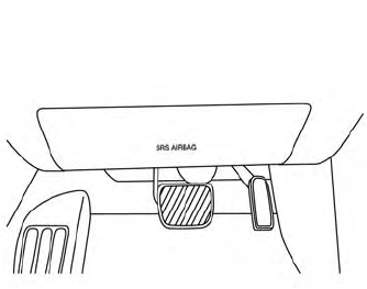
Driver’s side
The knee air bag is located in the knee bolster, on the driver’s and passenger’s side. All of the information, cautions and warnings in this manual apply and must be followed. The knee air bag is designed to inflate in higher severity frontal collisions, although it may inflate if the forces in another type of collision are similar to those of a higher severity frontal impact. It may not inflate in certain collisions.
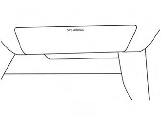
Passenger’s side
