Nissan Murano: Removal and Installation / Replacement Operations
WARNING:
-
The repair information in this section is intended for trained body repair technicians who have attained a high level of skill and experience (e.g. ASE Collision Repair Certification, I-CAR Professional Development Program [PDP] training, etc.) in repairing collision damaged Nissan Murano vehicles using appropriate tools and equipment. Performing repairs without the proper training, tools or equipment could damage the Nissan Murano vehicle or cause personal injury or death to you or others.
-
The information in this Body Repair Manual is a guideline for repairing collision damaged Nissan Murano vehicles. However, this information cannot cover all possible ways that a vehicle can be damaged. As such, the body repair technician is responsible for making sure that the repair does not affect the structural integrity or safety of the Nissan Murano vehicle. Improper repair of a damaged vehicle may result in a collision, property damage, personal injury or death.
-
Nissan recommends using only new genuine Nissan replacement body parts. Use of used, salvaged or aftermarket body parts is not recommended by Nissan. Non-genuine Nissan components may affect the Nissan Murano vehicle's structural integrity and crash safety performance, which could result in serious personal injury or death in an accident.
-
Technicians are encouraged to read the Body Repair Manual (Fundamentals) in order to ensure that the original functions and quality of the Nissan Murano vehicle are maintained. The Body Repair Manual (Fundamentals) contains additional information, including cautions and warnings, that are not included in this manual. Technicians should refer to both manuals to ensure proper repair.
-
Please note that this information is prepared for worldwide usage, and as such, certain procedures might not apply in some regions or countries.
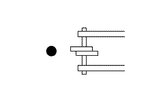
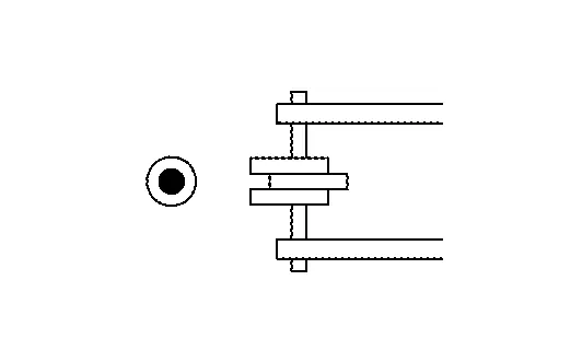
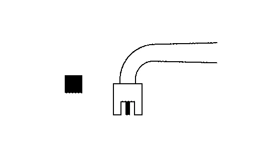
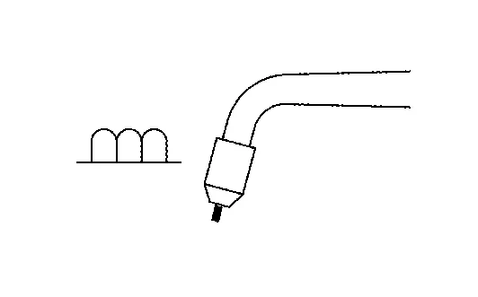
The symbols used in this section for welding operations are shown below.
| Symbol marks | Description | |
|---|---|---|
| "Number" |
"Number" after symbol mark is the total number of welds to apply. Example 1: ■"4"A = 4 MAG plug welds for 3-panel plug weld method. Example 2: "1" x20 (0.79) = 1 MAG seam weld by length 20 mm (0.79 in). "1" x20 (0.79) = 1 MAG seam weld by length 20 mm (0.79 in). |
|
|
|
2-panel spot weld |
|
|
|
3-panel spot weld | |
|
|
MAG plug weld |
|
|
For 3-panel plug weld method
|
||
|
|
MAG seam weld / Point weld |
|
|
|
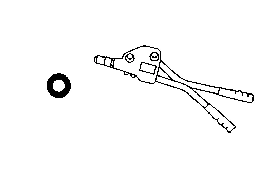
Rivet |
|

-
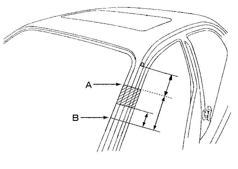
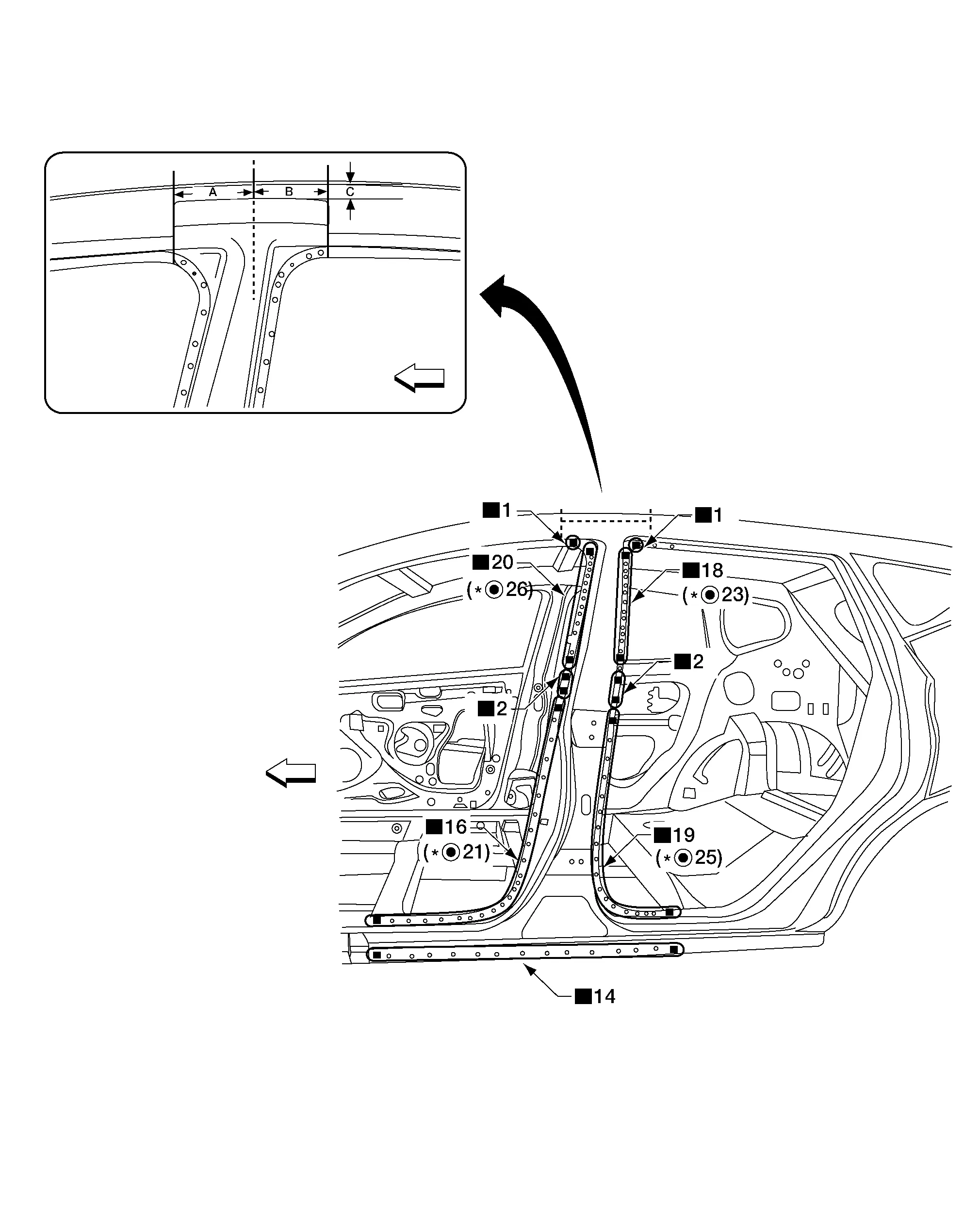
Front pillar butt joint can be determined anywhere within shaded area as shown in the figure. The best location for the butt joint is at position A due to the construction of the Nissan Murano vehicle.
-
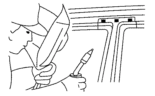
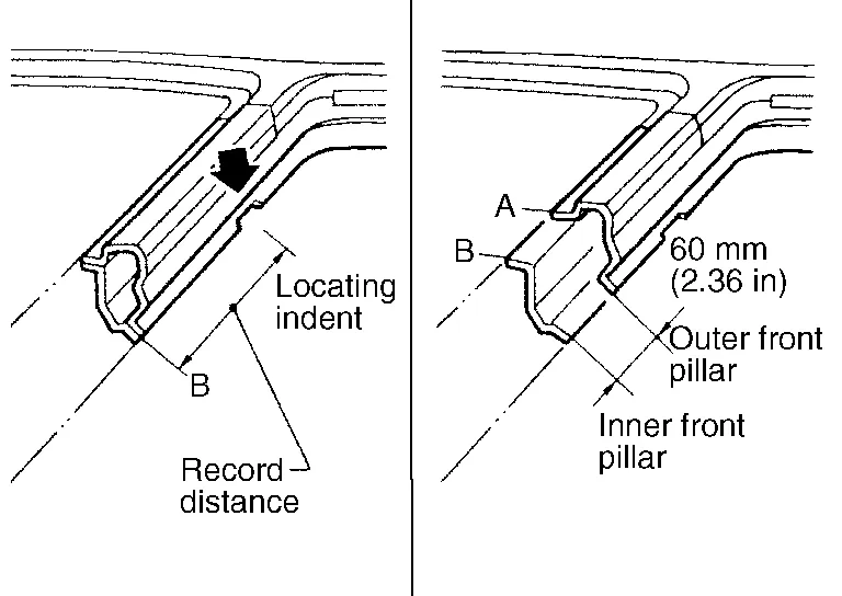
Determine cutting position and record distance from the locating indent. Use this distance when cutting the service part. Cut outer front pillar over 60 mm (2.36 in) above the inner front pillar cut position.
-
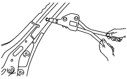
Prepare a cutting jig to make outer pillar easier to cut. Also, this will permit the service part to be accurately cut at the joint position.
-
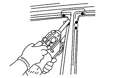
An example of cutting operation using a cutting jig is as per the following.
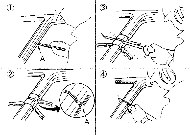
-
Mark cutting lines.
A: Cut position of outer pillar
B: Cut position of inner pillar
-
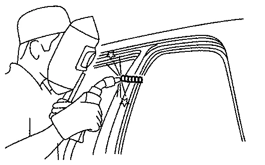
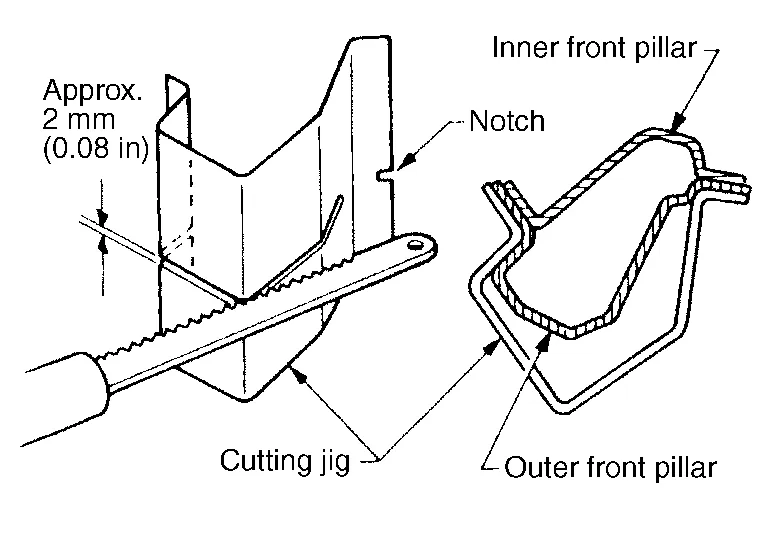
Align cutting line with notch on jig. Clamp jig to pillar.
-
Cut outer pillar along groove of jig (at position A).
-
Remove jig and cut remaining portions.
-
Cut inner pillar at position B in same manner.
| Replacement parts | |||||
| • | Upper radiator core support | • | Hoodledge | • | Hoodledge reinforcement |
| Front | |||||
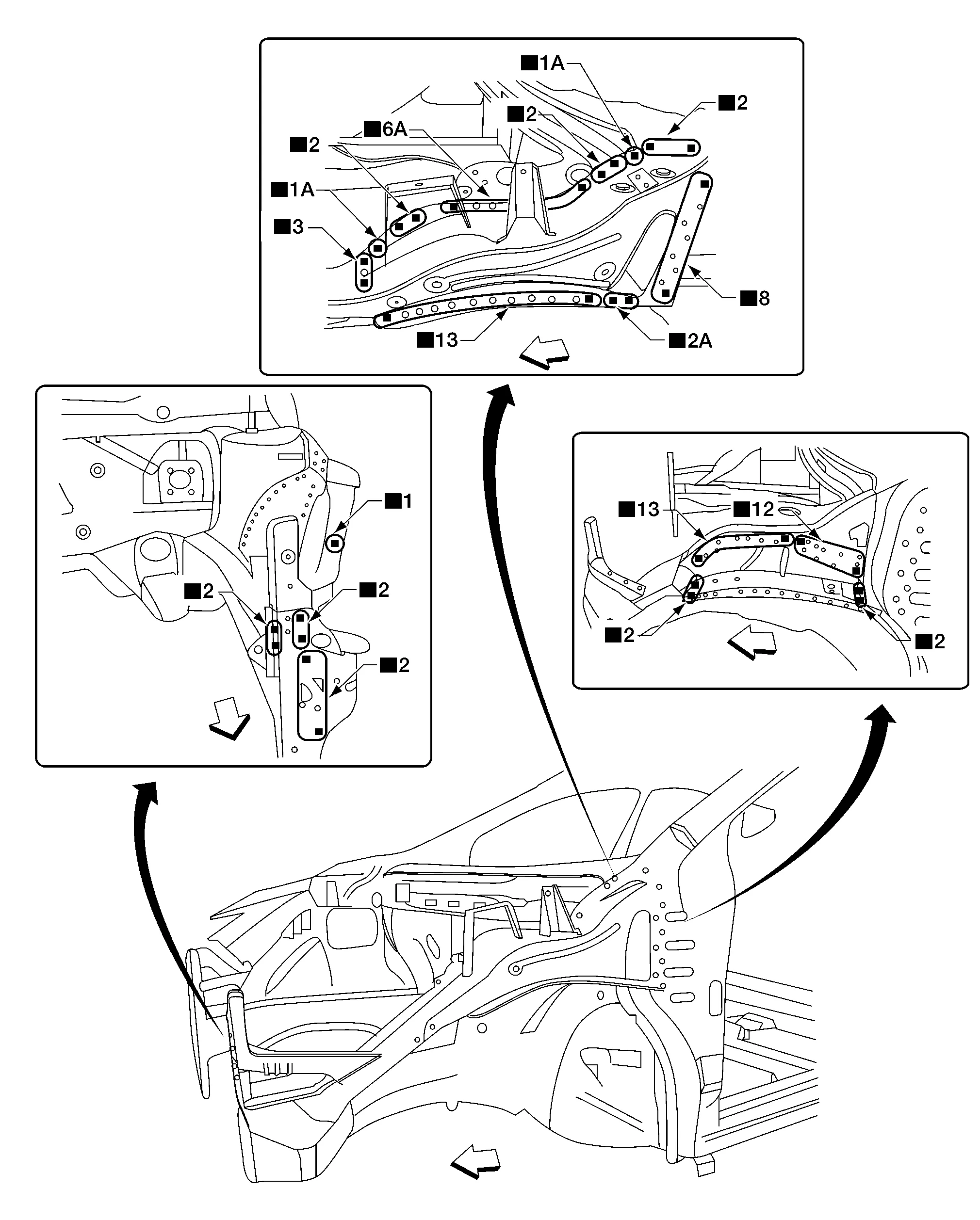
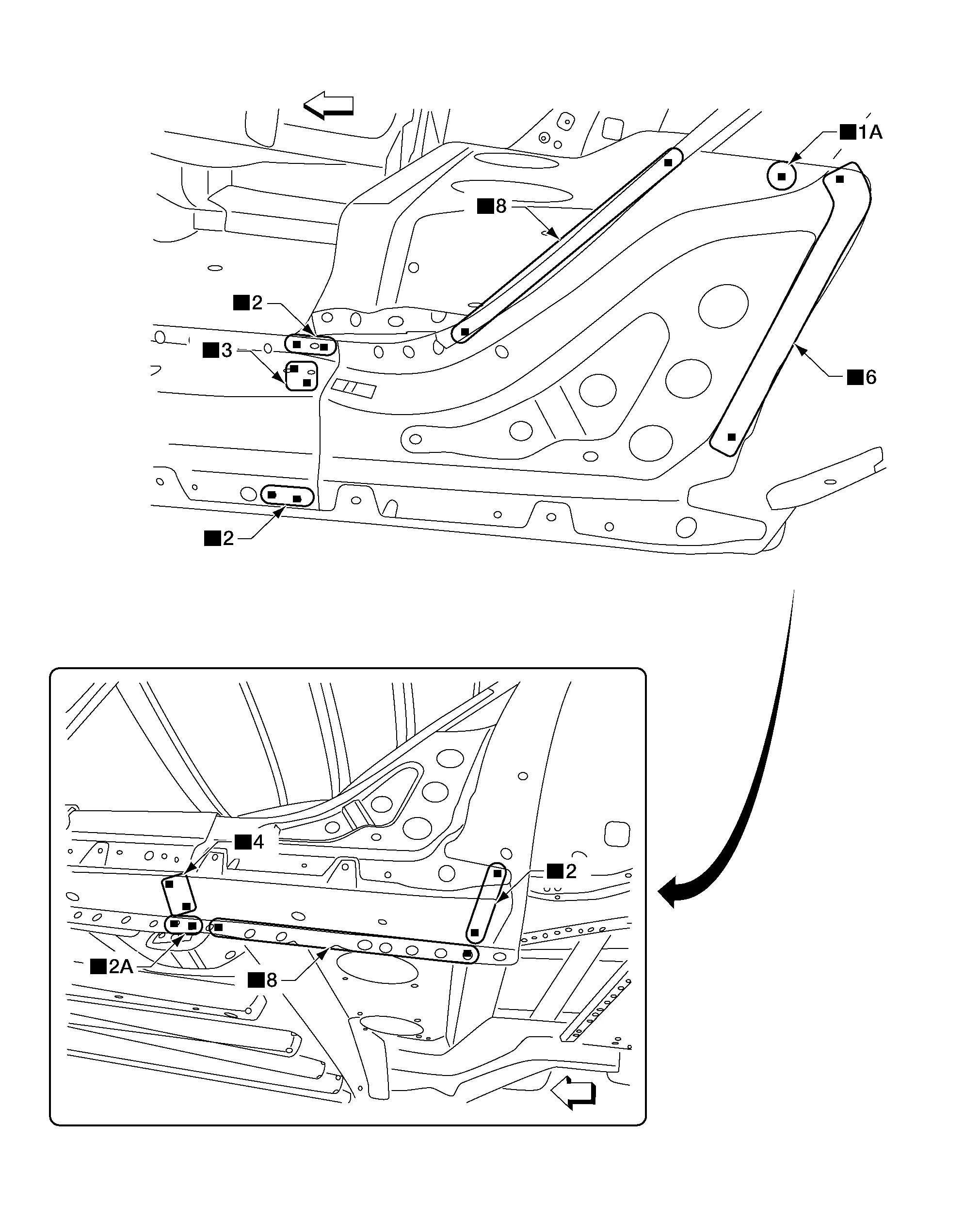
Front Strut Housing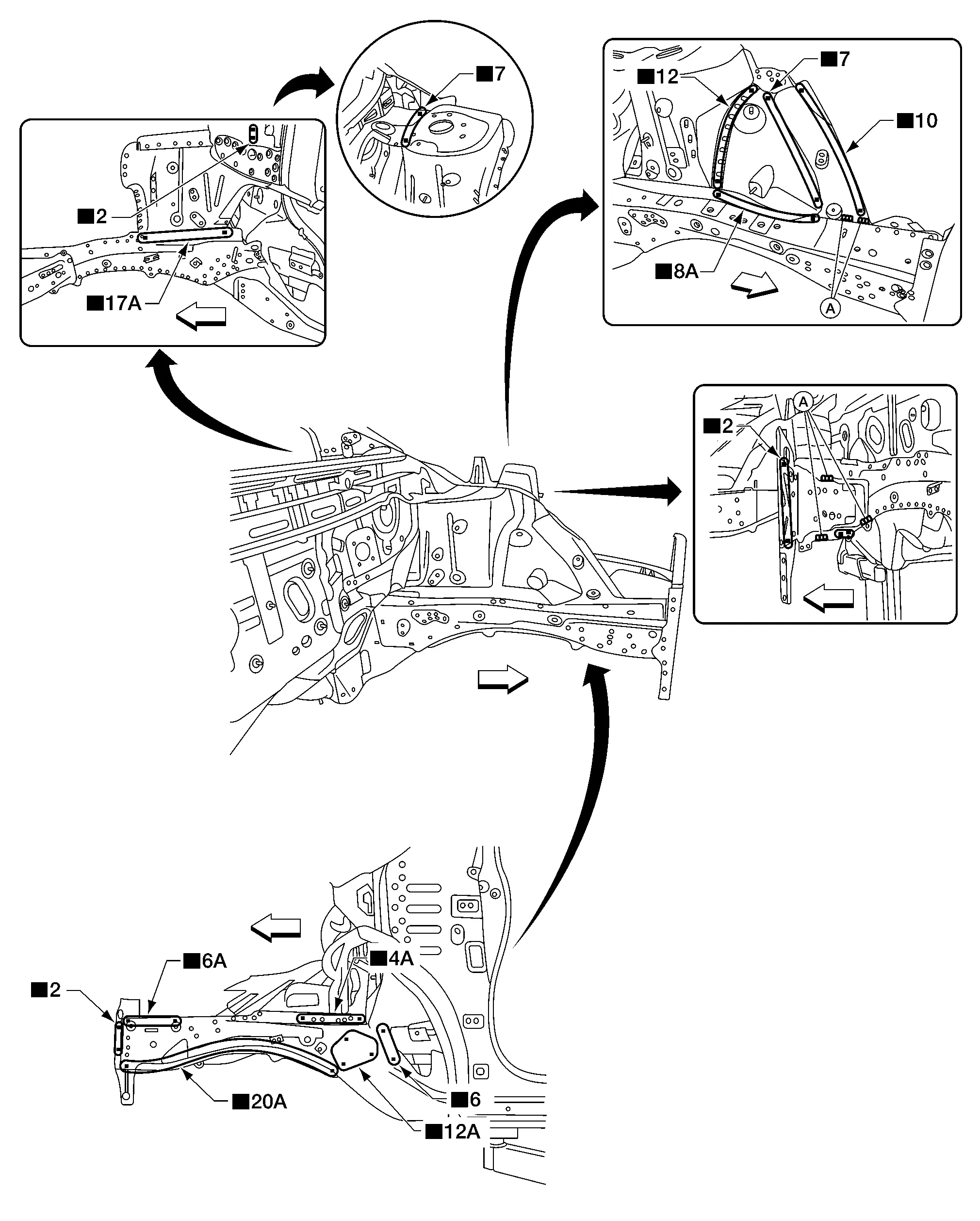
| Replacement parts | |||||
| • | Front strut housing | • | Front strut housing extension | • | Front side member extension |
| • | Front side member closing plate | A. | MAG weld | Front | |
Work after the hoodledge assembly and front suspension spring support assembly has been removed.
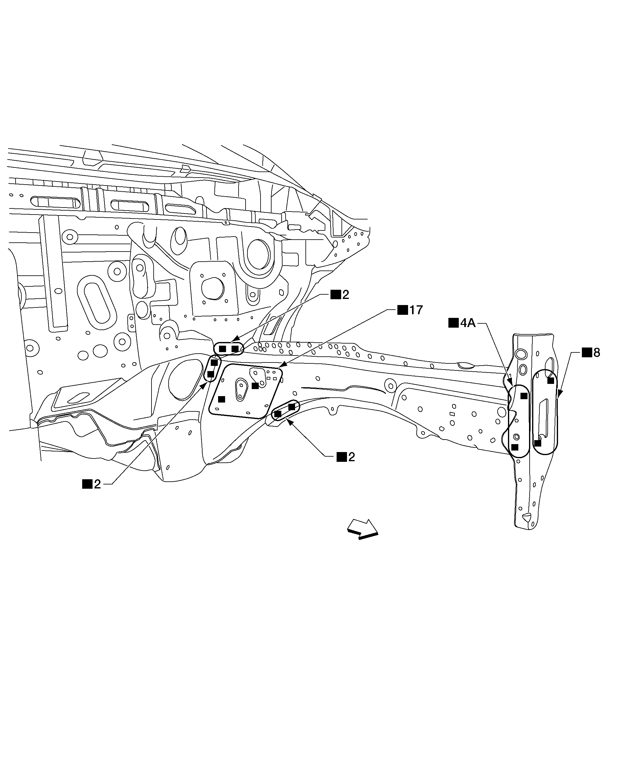
| Replacement parts | |||||
| • | Front side member | • | Front side member extension | Front | |
OUTER
-
Work after the upper hoodledge has been removed.
| Replacement parts | |||||
| • | Front pillar section of front body side outer | Front | |||
 |
For spot welding of steel plate of strength 980 MPa, observe the indicated welding conditions. Refer to Welding of Ultra High Strength Steel. | ||||
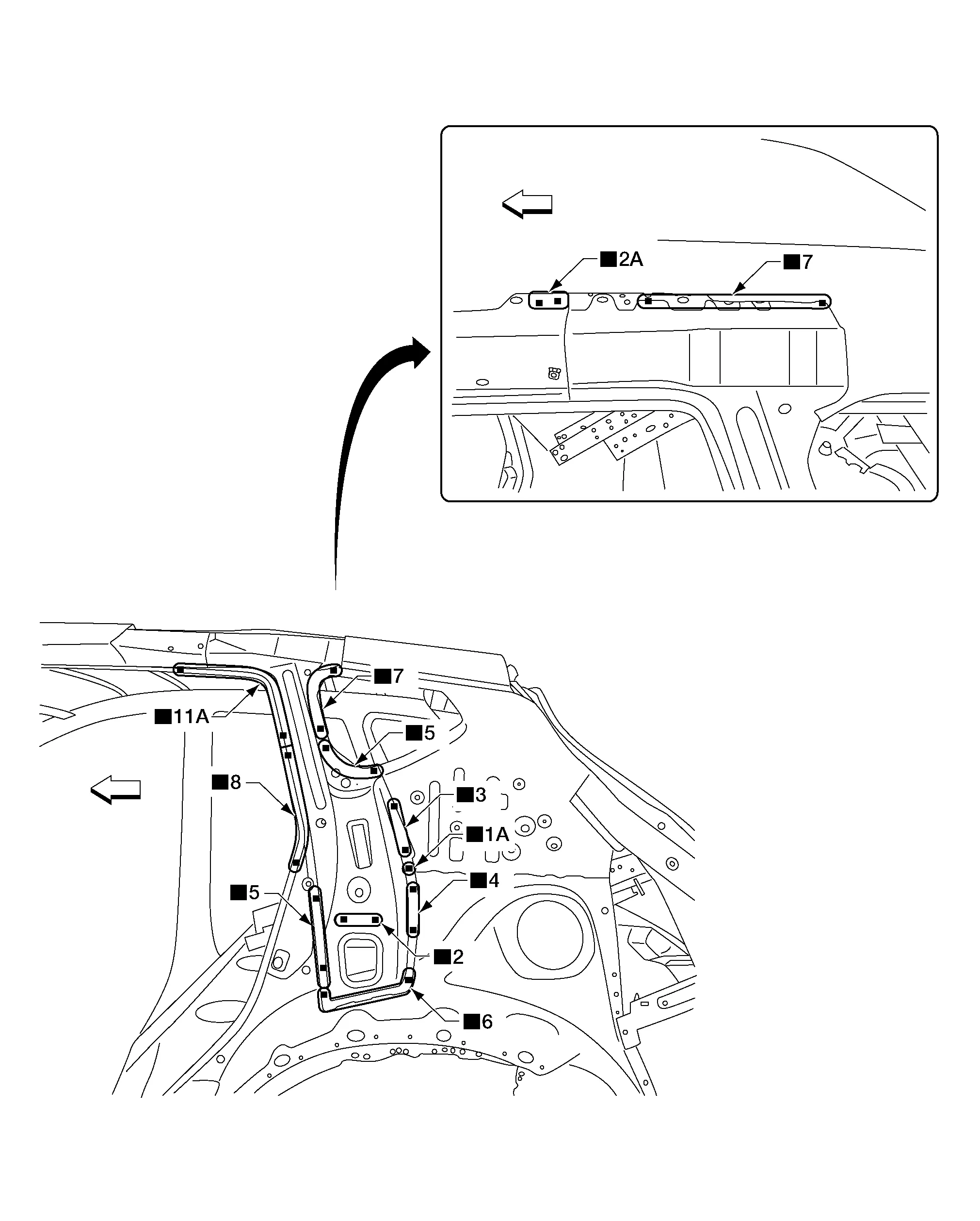
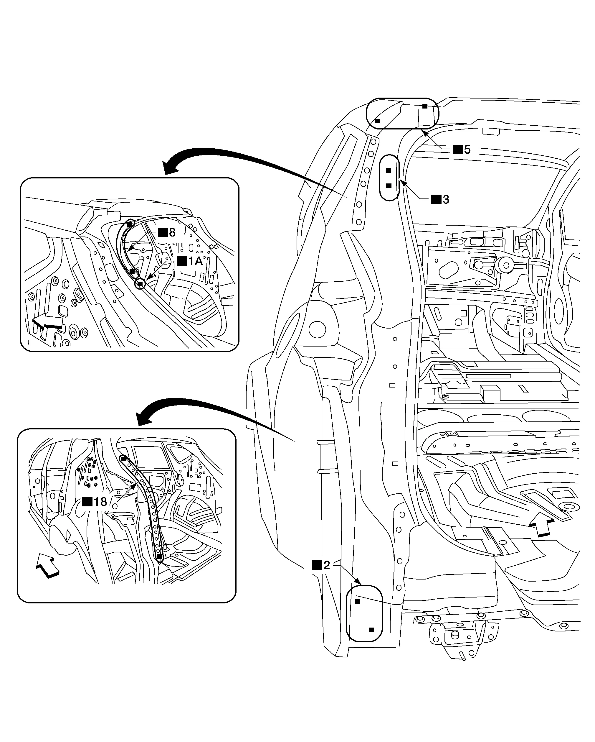
HINGE PILLAR BRACE
Upper
-
Work after front pillar outer has been removed.
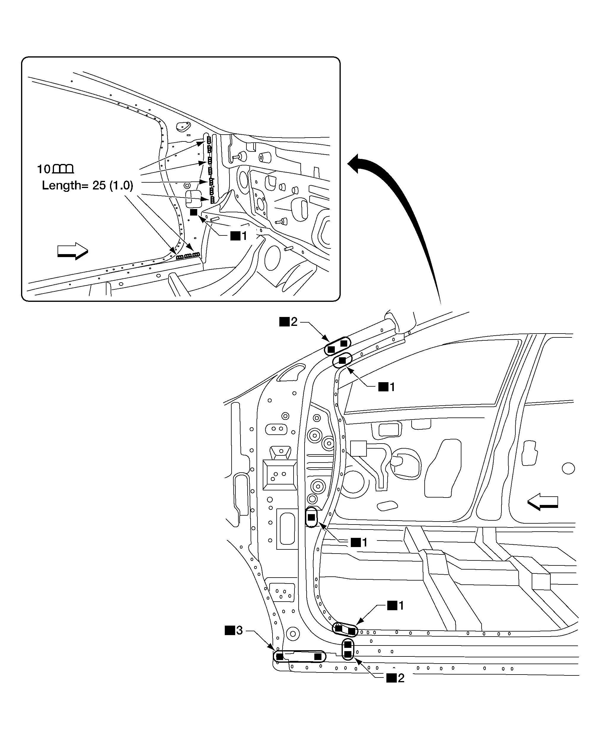
Unit: mm (in)
| Replacement parts | |||||
| • | Front pillar upper hinge brace | Front | |||
Work after the front pillar portion of body side inner reinforcement and the front pillar lower hinge brace have been removed.
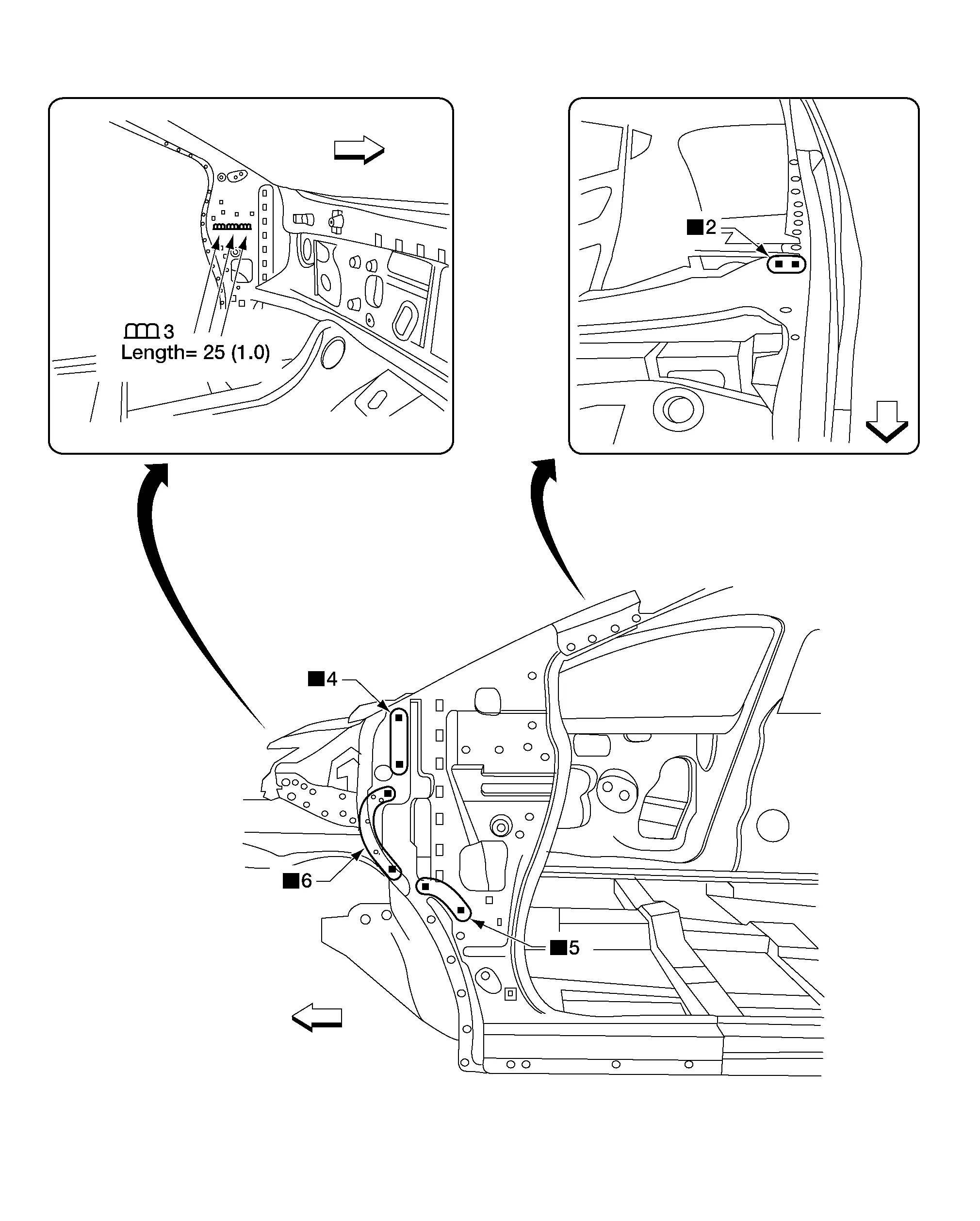
Unit: mm (in)
| Replacement parts | |||||
| • | Dash side | Front | |||
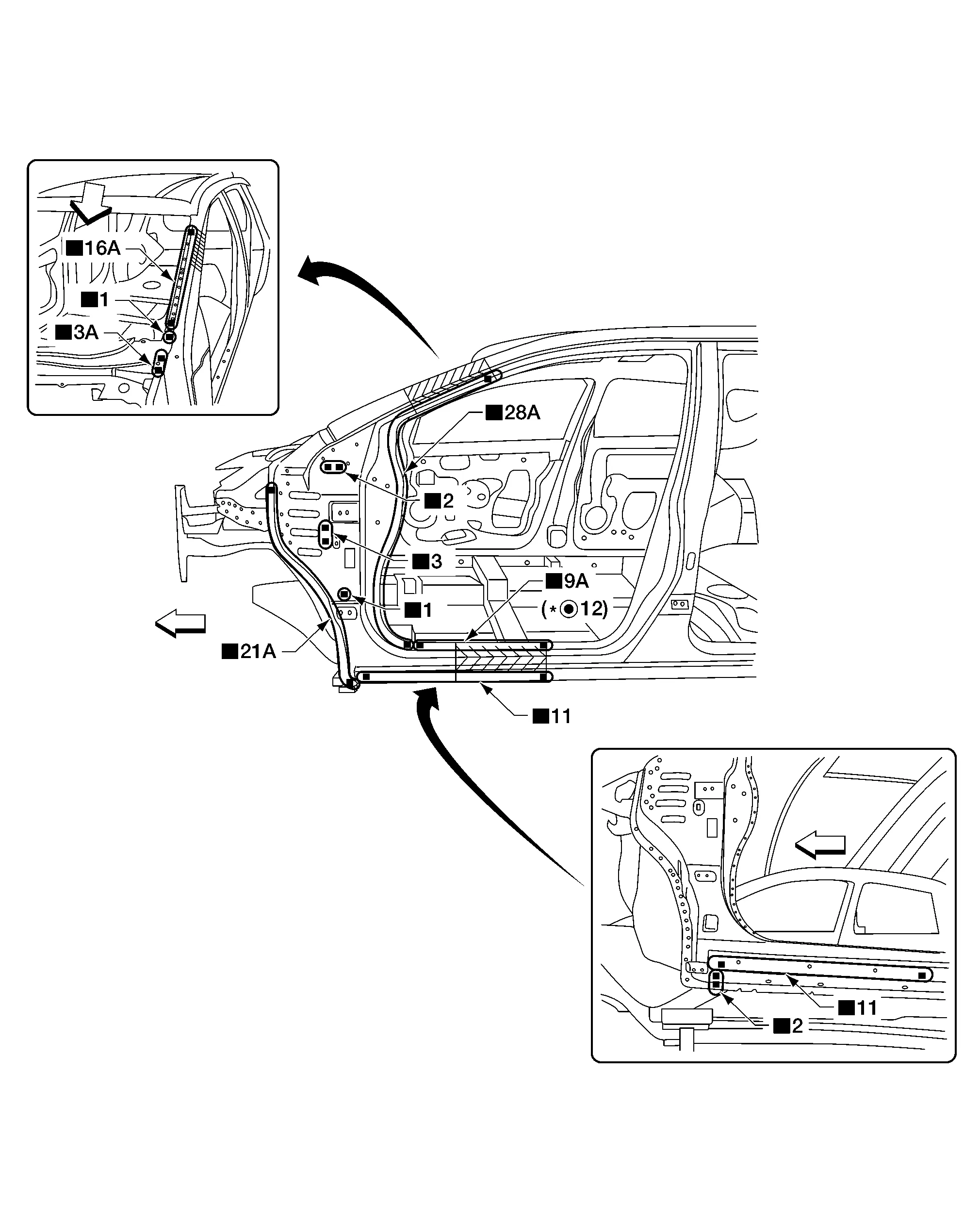
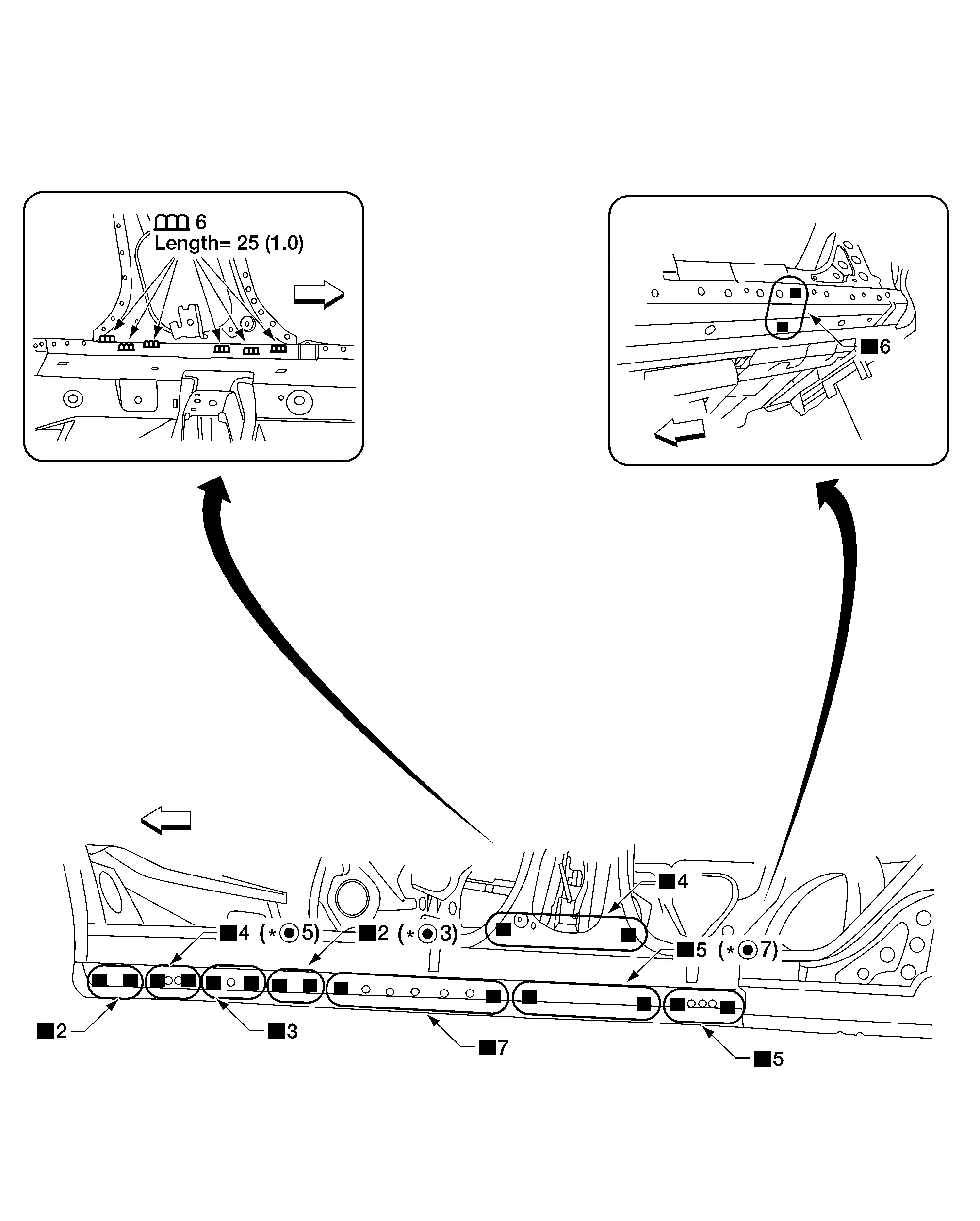
OUTER
Unit: mm (in)
| Replacement parts | |||||
|---|---|---|---|---|---|
| • | Center pillar portion of front body side outer | A. | 130 (5.12) | B. | 110 (4.33) |
| C. | 50 (1.97) | Front | |||
|
For spot welding of steel plate of strength 980 MPa, observe the indicated welding conditions. Refer to Welding of Ultra High Strength Steel. | ||||
REINFORCEMENT
Work after center pillar portion of front body side outer has been removed.
| Replacement parts | |||||
|---|---|---|---|---|---|
| • | Center pillar reinforcement | Front | |||
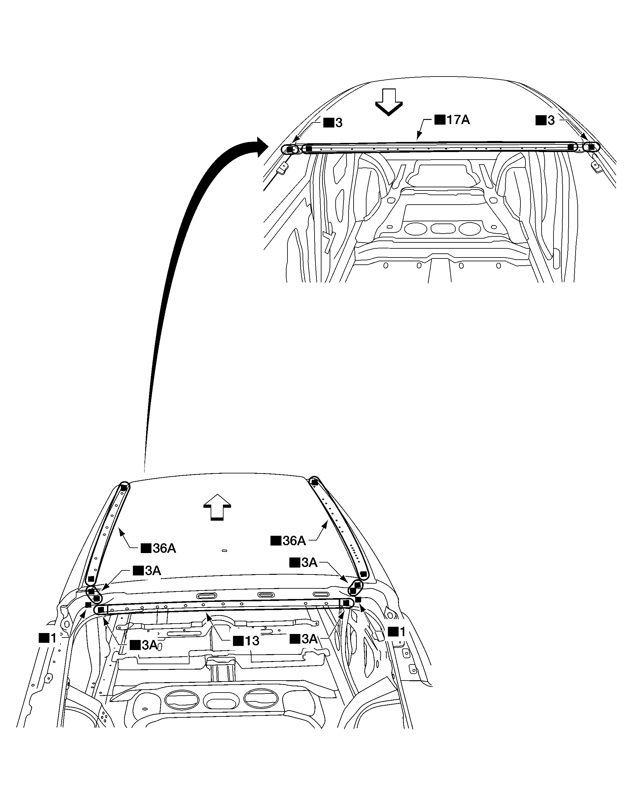
| Replacement parts | |||||
| • | Roof panel | Front | |||
Moon Roof
| Replacement parts | |||||
| • | Roof panel, Moon roof shown | Front | |||
| Replacement parts | |||||
| • | Rear fender | Front | |||
|
For spot welding of steel plate of strength 980 MPa, observe the indicated welding conditions. Refer to Welding of Ultra High Strength Steel. | ||||
Work after the front pillar lower hinge brace and the center pillar reinforcement have been removed.
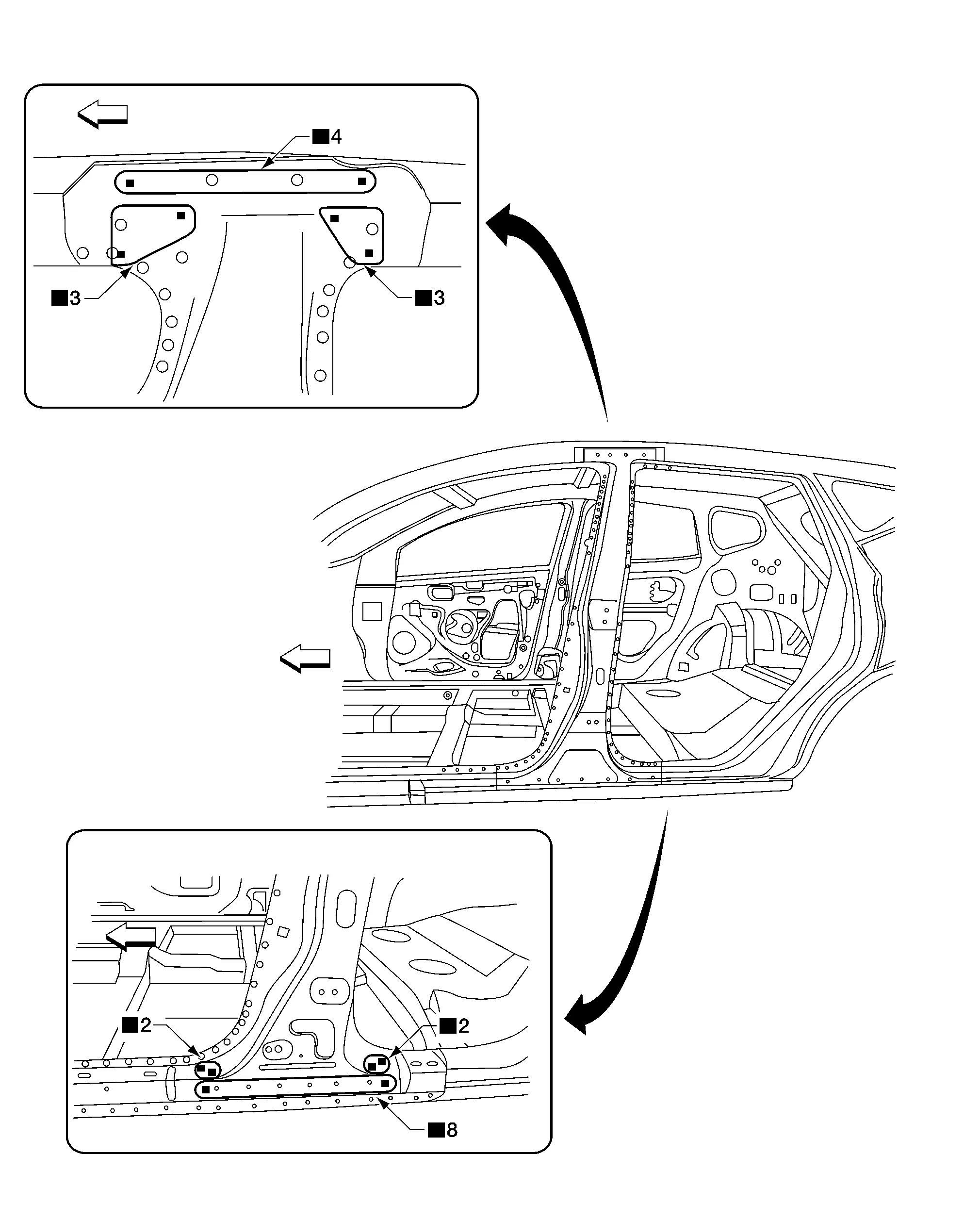
| Replacement parts | |||||
| • | Sill outer reinforcement | Front | |||
|
For spot welding of steel plate of strength 980 MPa, observe the indicated welding conditions. Refer to Welding of Ultra High Strength Steel. | ||||
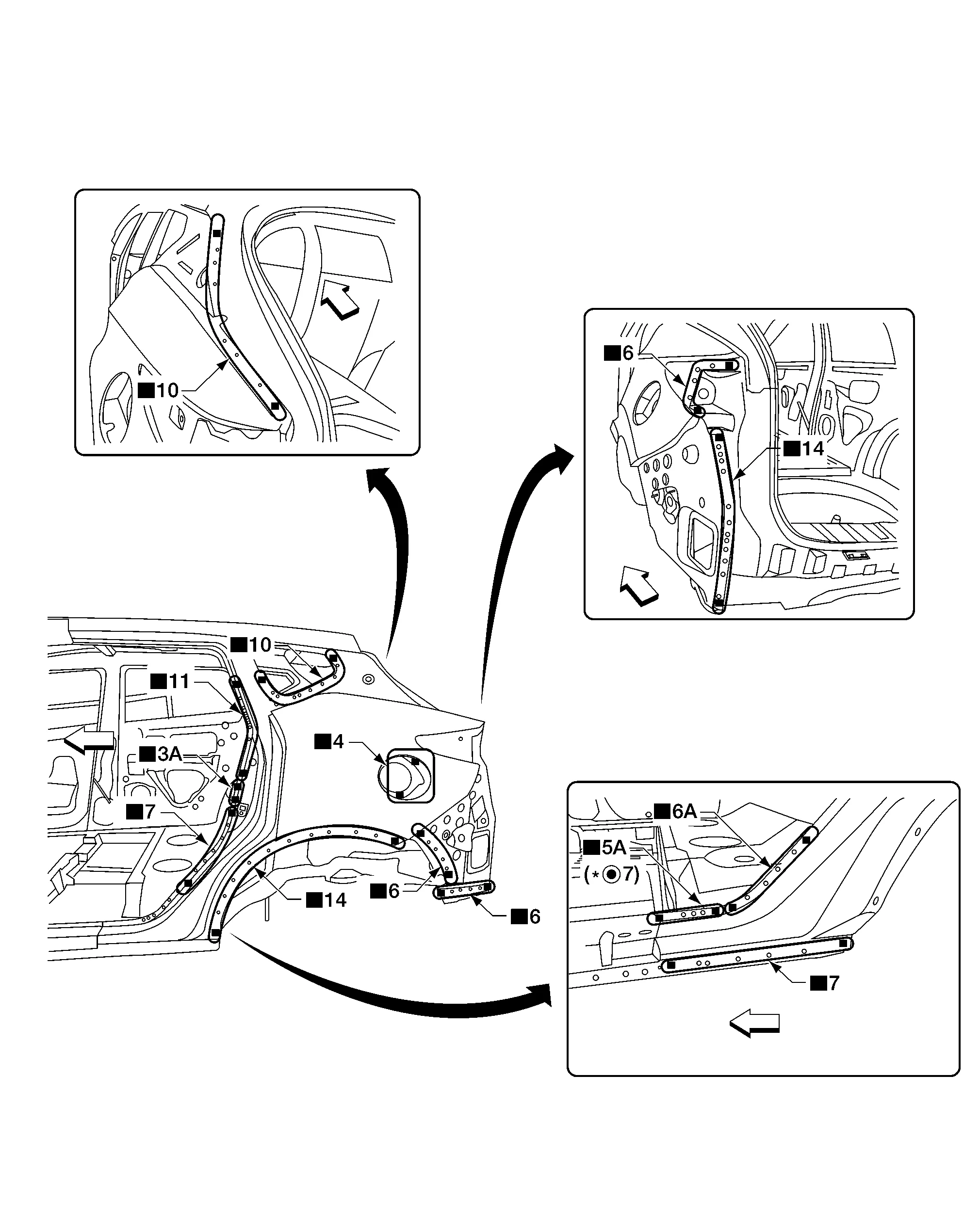
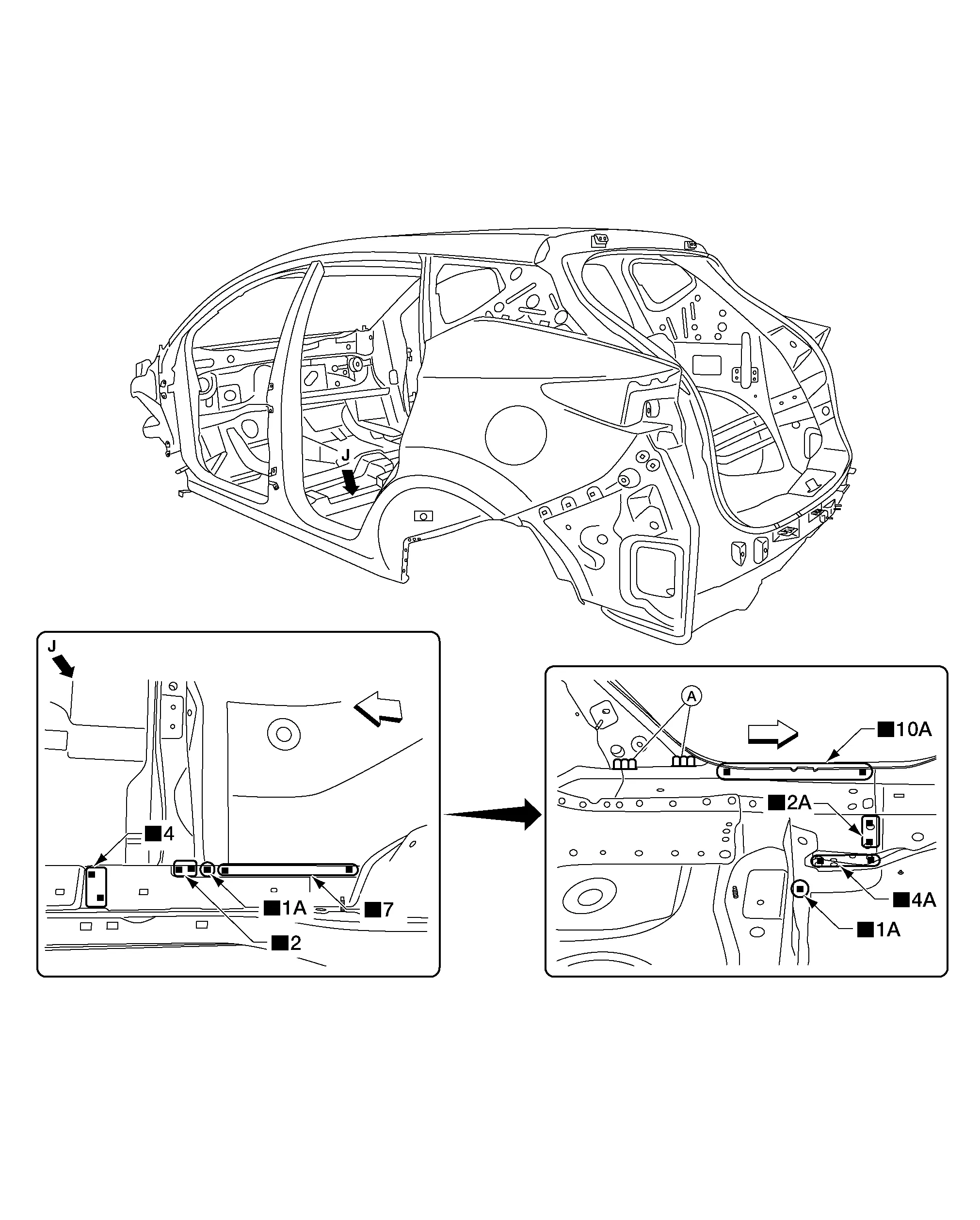
Work after the Rear Fender has been removed.
| Replacement parts | |||||
| • | Sill outer reinforcement extension | Front | |||
|
For spot welding of steel plate of strength 980 MPa, observe the indicated welding conditions. Refer to Welding of Ultra High Strength Steel. | ||||
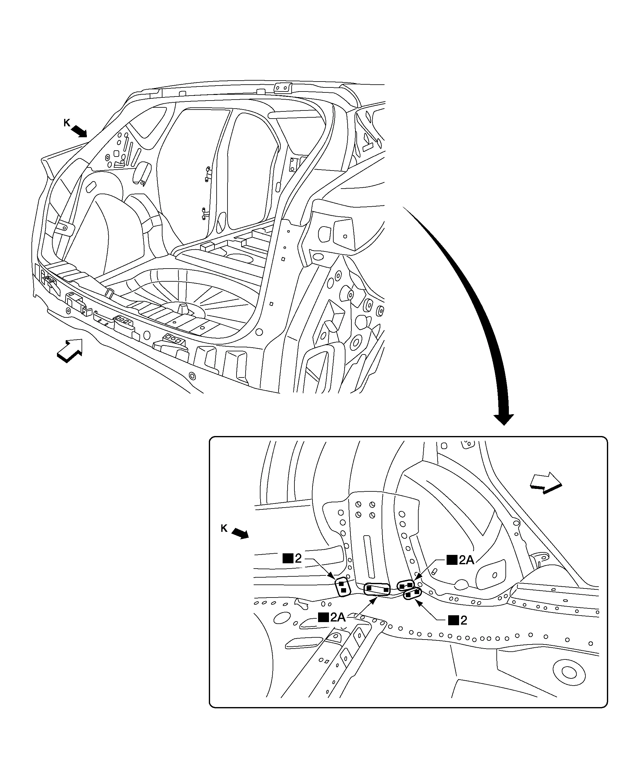
Work after the Rear Fender has been removed.
| Replacement parts | |||||
| • | Back Pillar Reinforcement | Front | |||
|
For spot welding of steel plate of strength 980 MPa, observe the indicated welding conditions. Refer to Welding of Ultra High Strength Steel. | ||
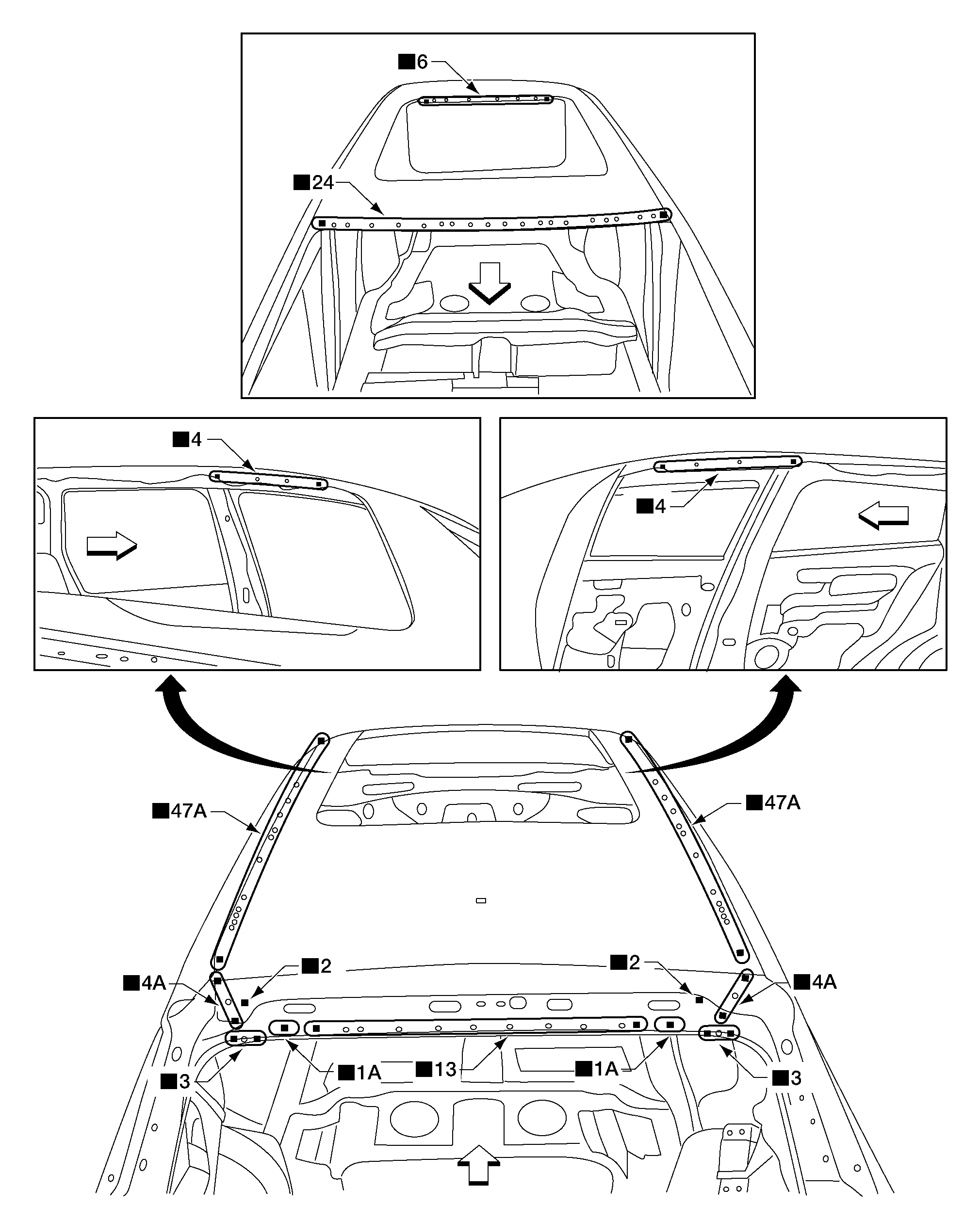
Work after the Rear Fender and the Back Pillar Reinforcement and Rear Side Member have been removed.
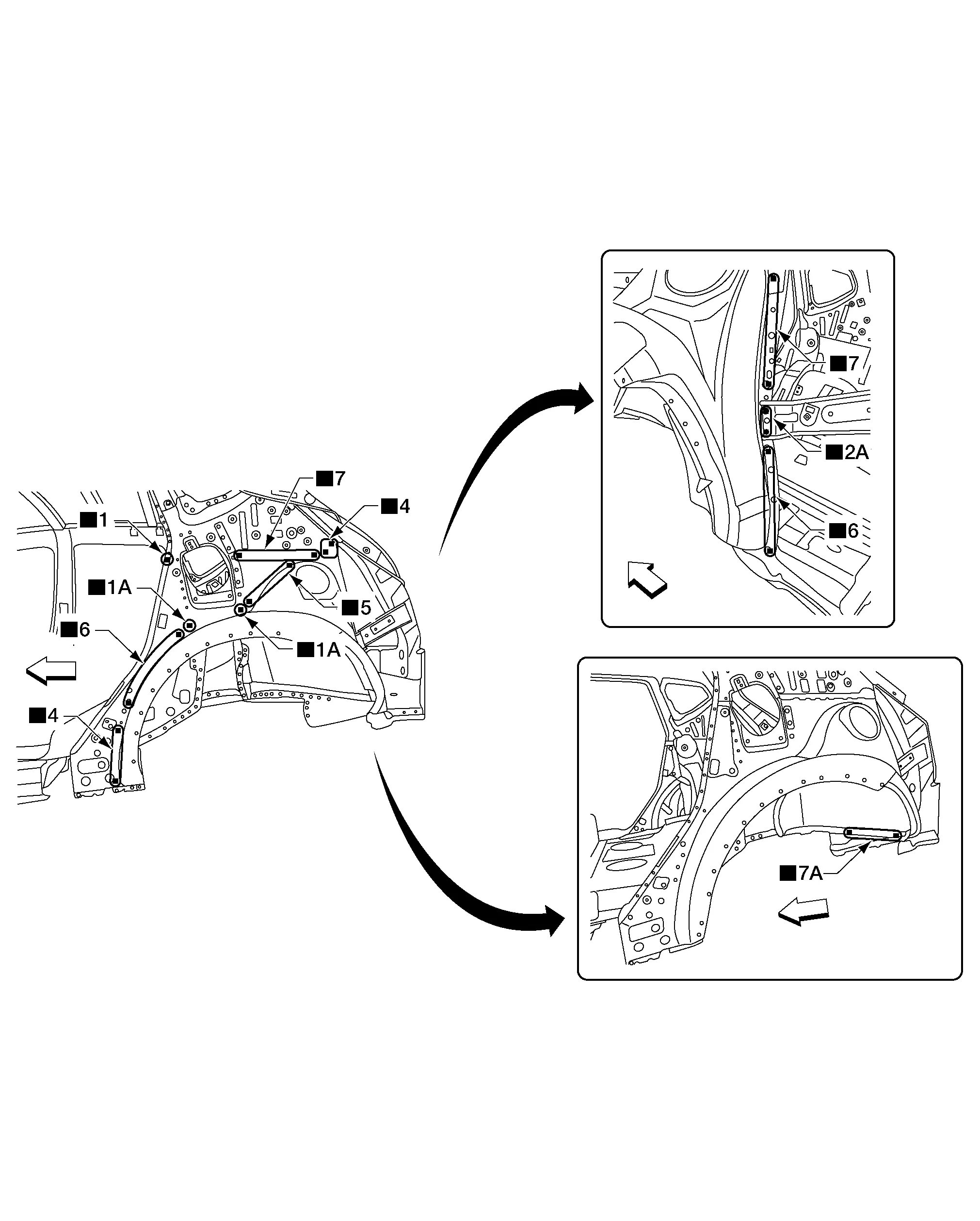
| Replacement parts | |||||
| • | Wheelhouse inner and outer | Front | |||
|
For spot welding of steel plate of strength 980 MPa, observe the indicated welding conditions. Refer to Welding of Ultra High Strength Steel. | ||||
-
Work after rear body side outer has been removed.
| Replacement parts | |||||
| • | Rear pillar assembly | Front | |||
-
Work after rear panel assembly has been removed.
| Replacement parts | |||||
| • | Rear floor rear (Partial Replacement) | Front | |||
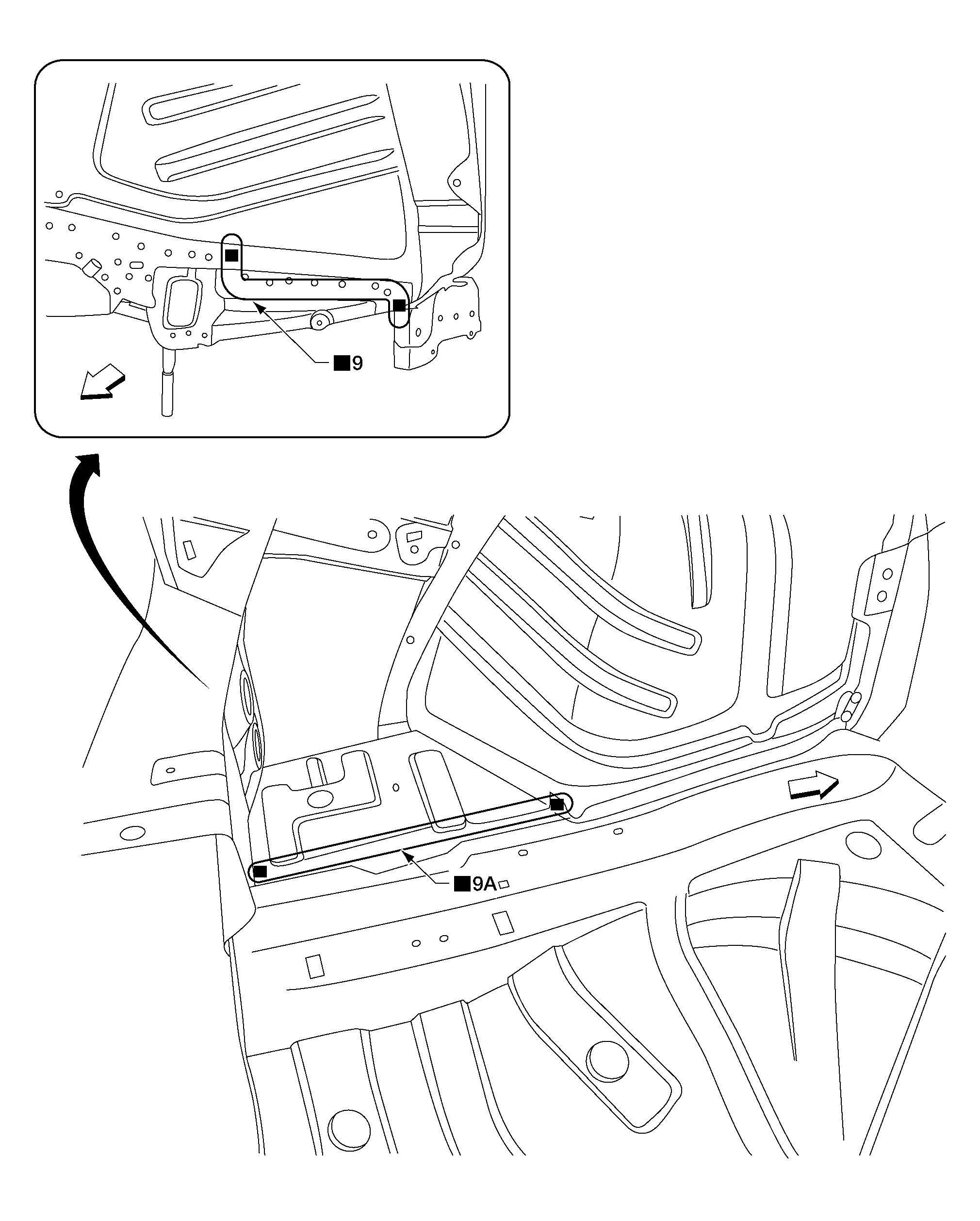
| Replacement parts | |||||
|---|---|---|---|---|---|
| • | Rear floor side (RH, LH) | Front | |||
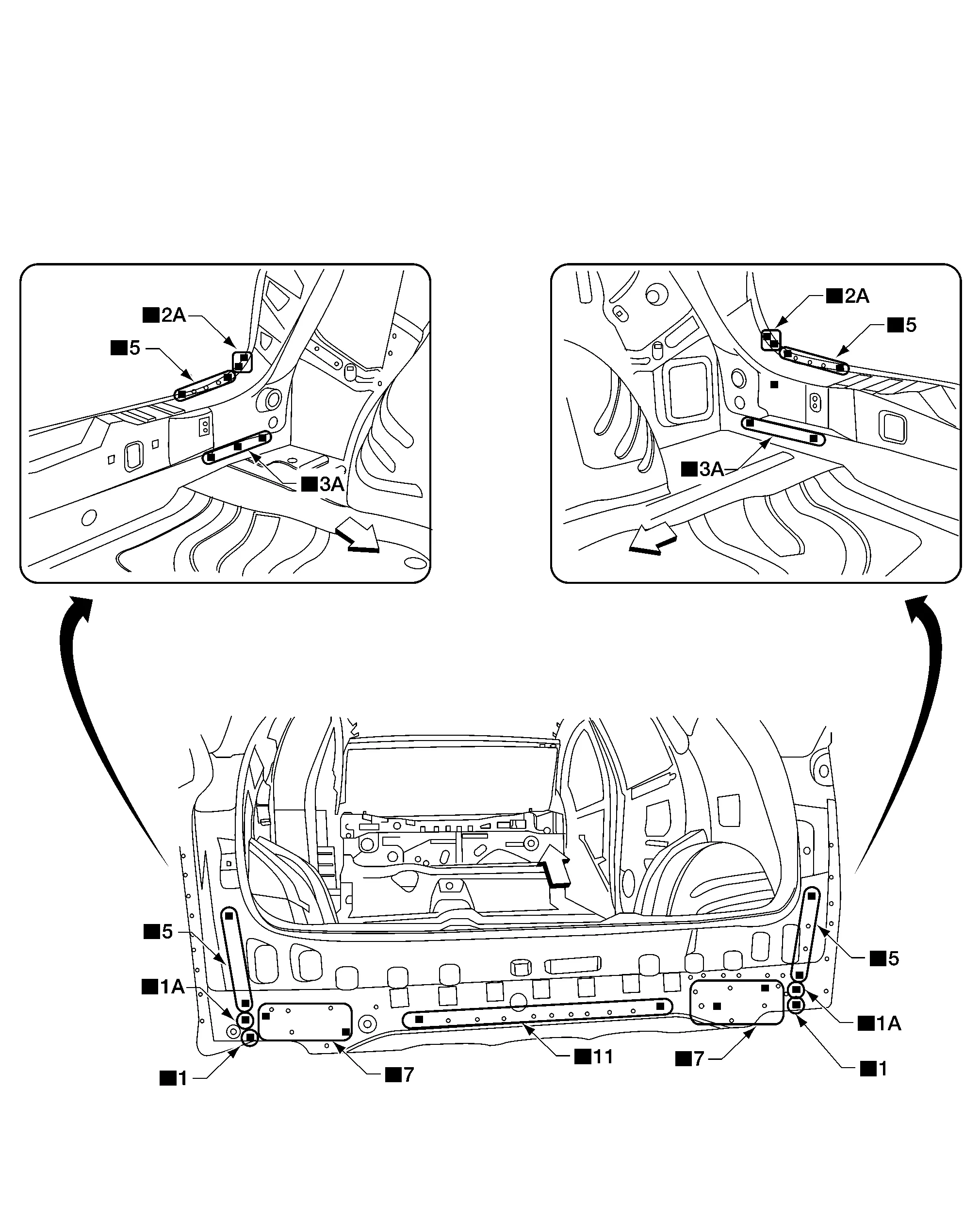
| Replacement parts | |||||
| • | Rear panel assembly | Front | |||
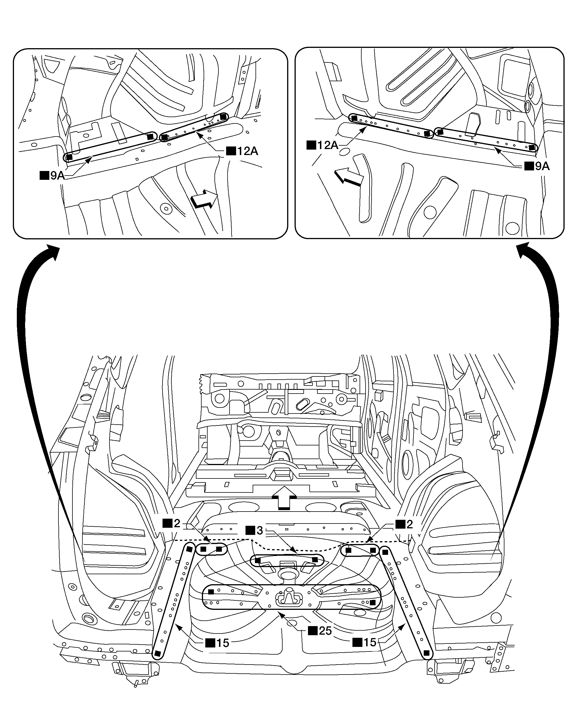
-
Work after rear panel assembly has been removed.
| Replacement parts | |||||
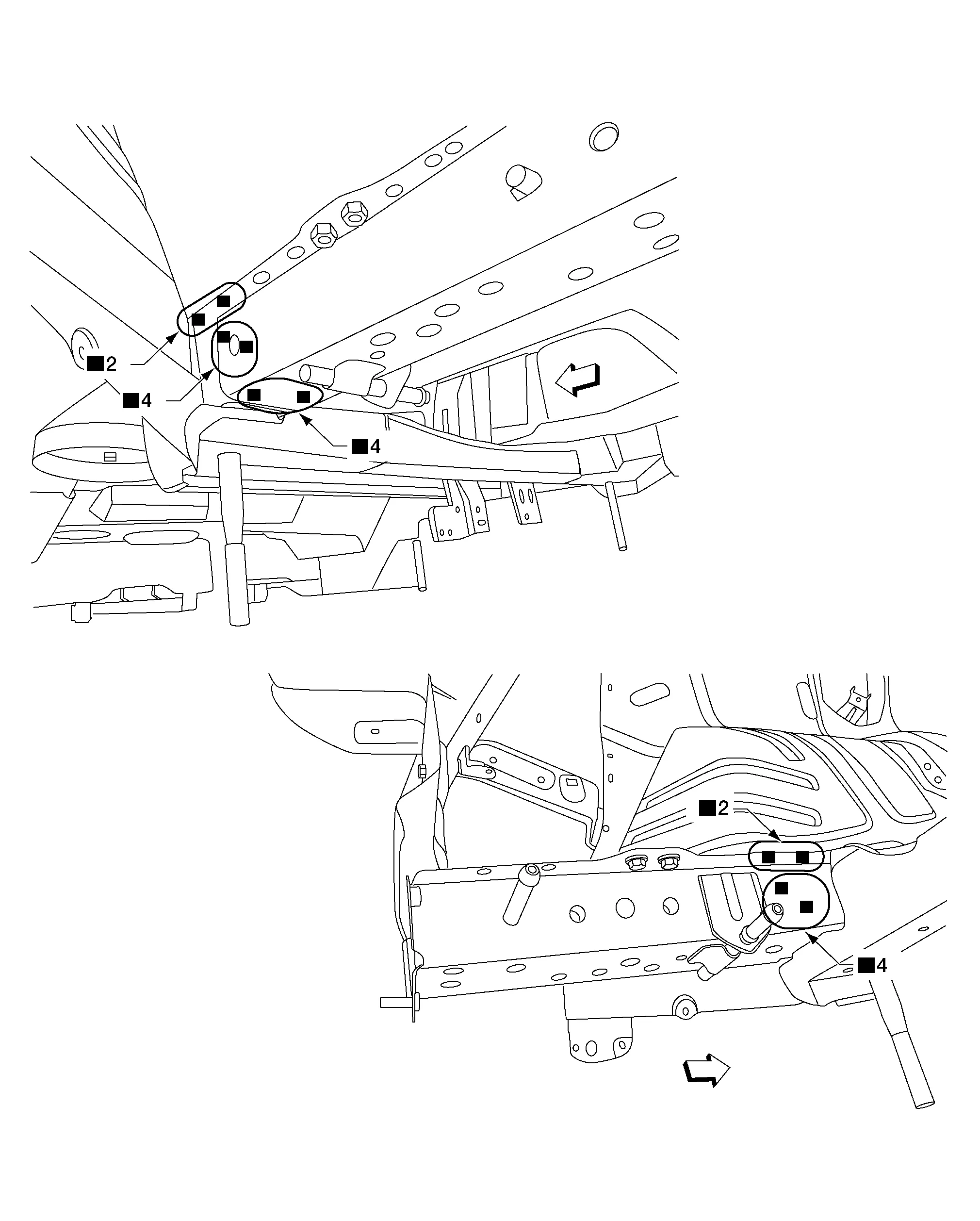
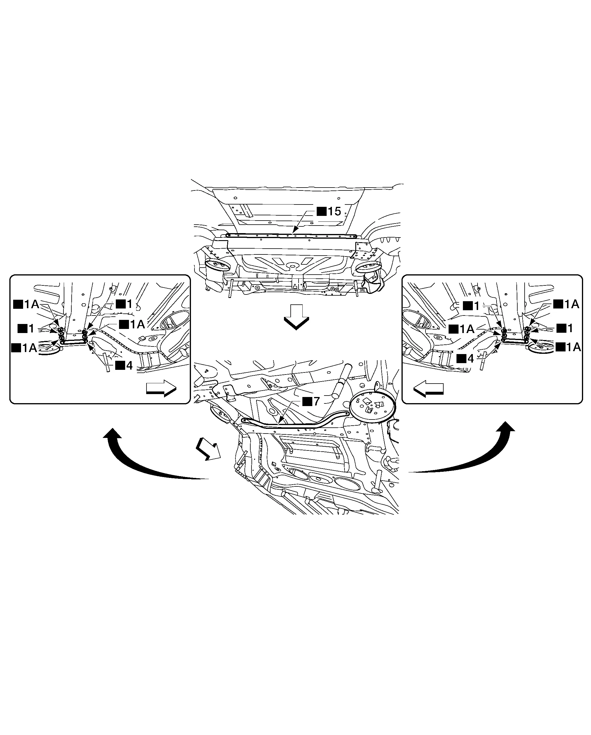
| • | Rear side member extension | Front | |||
| Replacement parts | |||||
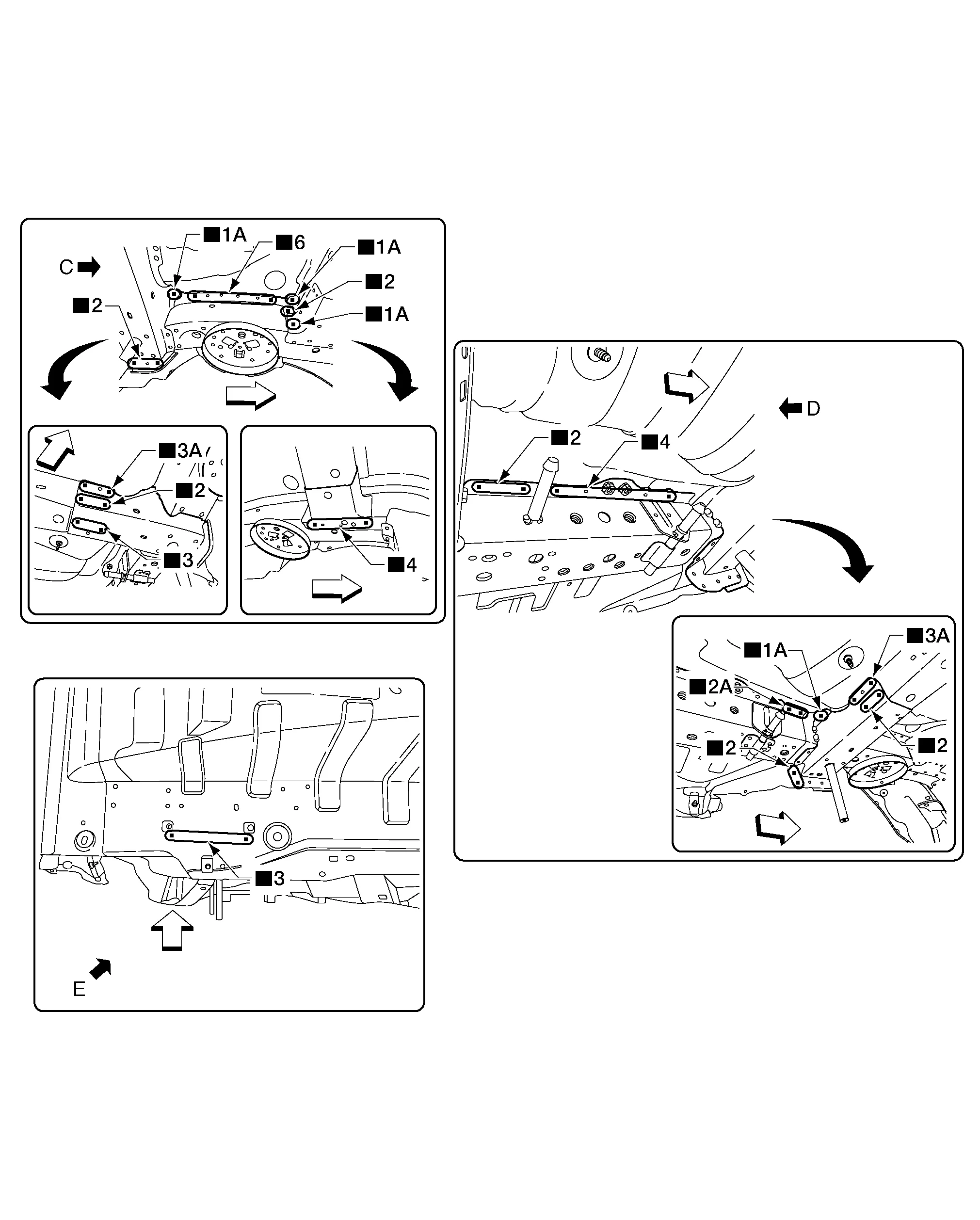
| • | Rear cross member assembly | Front | |||

| Front | |||||
| Front | |||||
| Front | |||||
| Front | |||||
| A. | MAG Weld | ||||
| Front | |||||
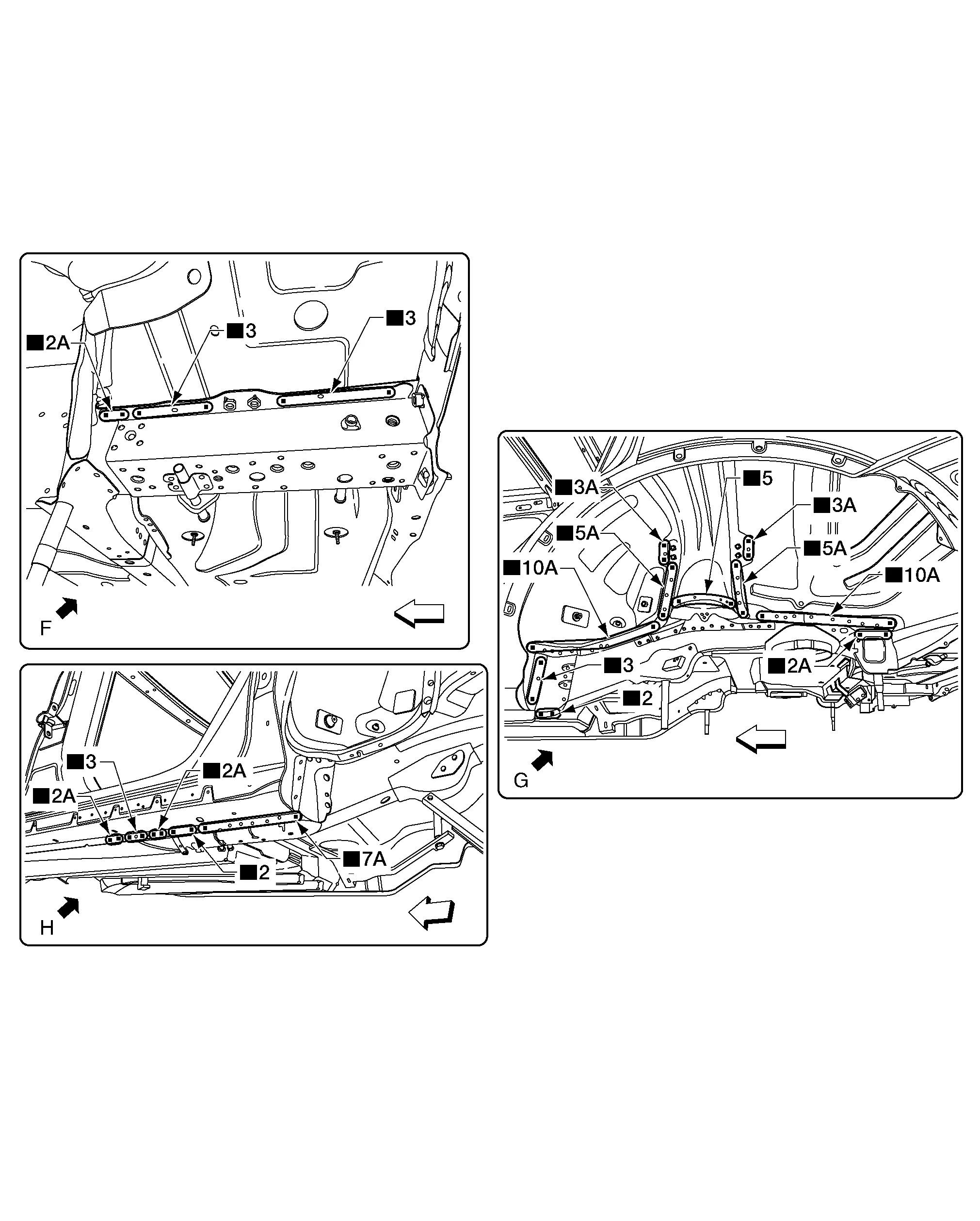
| Replacement parts | |||||
| • | Rear Cross Member Assembly | • | Rear Side Member (LH) | ||
 Body Construction
Body Construction
1.
Body side outer
2.
Front pillar inner upper
3.
Upper front pillar reinforcement
4.
Dash side inner
5.
Front hinge pillar lower reinforcement
6...
 Service Data and Specifications (sds). Body Alignment
Body Center Marks
Factory marks exist on certain parts of the body to indicate the vehicle center. When repairing the Nissan Murano vehicle frame (members, pillars, etc...
Other information:
Nissan Murano (Z52) 2015-2024 Service Manual: Diagnosis and Repair Workflow
Work Flow OVERALL SEQUENCEDETAILED FLOWGET INFORMATION FOR SYMPTOM Get detailed information from the customer about the symptom (the condition and the environment when the incident/malfunction occurred). >> GO TO 2. CONFIRM THE SYMPTOM Try to confirm the symptom described by the customer...
Nissan Murano (Z52) 2015-2024 Service Manual: Around View Monitor Control Unit
Exploded View 1. Instrument panel assembly 2. Around view monitor control unit Removal and Installation REMOVALNOTE: Before replacing around view monitor control unit, perform “Before Replace ECU” of “Read / Write Configuration” to save or print current Nissan Murano vehicle specification...
Categories
- Manuals Home
- Nissan Murano Owners Manual
- Nissan Murano Service Manual
- Memory storage function (key-link)
- Shift lock release
- GAS STATION INFORMATION
- New on site
- Most important about car
Unfastening the seat belts. Checking seat belt operation
Unfastening the seat belts

To unfasten the seat belt, press the button
on the buckle  . The seat belt
automatically
retracts.
. The seat belt
automatically
retracts.