Nissan Murano: Dtc/circuit Diagnosis / P1078 Evt Control Position Sensor
DTC DETECTION LOGIC
An excessively high or low voltage from the sensor is sent to ECM.
| DTC |
CONSULT screen terms (Trouble diagnosis content) |
DTC detection condition | |
| P1078 |
EXH TIM SEN/CIRC-B1 [Exhaust valve timing (EVT) control position sensor (bank 1) circuit] |
Diagnosis condition | Start engine and let it idle |
| Signal (terminal) | Voltage signal transmitted from EVT control position sensor to ECM | ||
| Threshold | An excessively high or low voltage from the sensor is sent to ECM | ||
| Diagnosis delay time | — | ||
| P1084 |
EXH TIM SEN/CIRC-B2 [Exhaust valve timing (EVT) control position sensor (bank 2) circuit] |
Diagnosis condition | Start engine and let it idle |
| Signal (terminal) | Voltage signal transmitted from EVT control position sensor to ECM | ||
| Threshold | An excessively high or low voltage from the sensor is sent to ECM | ||
| Diagnosis delay time | — | ||
POSSIBLE CAUSE
DTC P1078
-
Harness or connectors [EVT control position sensor (bank 1) circuit is open or shorted.]
-
EVT control position sensor
-
Crankshaft position (CKP) sensor
-
Camshaft position (CMP) sensor (bank 1)
-
Accumulation of debris to the signal pick-up portion of the camshaft
DTC P1084
-
Harness or connectors [EVT control position sensor (bank 2) circuit is open or shorted.]
-
EVT control position sensor (bank 2)
-
Each sensor, connected with sensor power supply 2 circuit
-
Accumulation of debris to the signal pick-up portion of the camshaft
CHECK DTC PRIORITY
If DTC P1078 or P0184 is displayed with DTC P0643, first perform the confirmation procedure (trouble diagnosis) for DTC P0643.
Is applicable DTC detected?
YES>>Perform diagnosis of applicable. Refer to DTC Description.
NO>>GO TO 2.
PRECONDITIONING
If DTC Confirmation Procedure has been previously conducted, always perform the following procedure before conducting the next test.
-
Turn ignition switch OFF and wait at least 10 seconds.
-
Turn ignition switch ON.
-
Turn ignition switch OFF and wait at least 10 seconds.
>>
GO TO 3.
PERFORM DTC CONFIRMATION PROCEDURE
-
Start engine and let it idle for 10 seconds.
-
Check 1st trip DTC.
Is 1st trip DTC detected?
YES>>Proceed to Diagnosis Procedure.
NO>>To check malfunction symptom before repair: Refer to Intermittent Incident.
NO>>Confirmation after repair: INSPECTION END
CHECK DTC PRIORITY
If DTC P1078 or P1084 is displayed with DTC P0643, first perform the confirmation procedure (trouble diagnosis) for DTC P0643.
Is applicable DTC detected?
YES>>Perform diagnosis of applicable. Refer to DTC Description.
NO>>GO TO 2.
CHECK EXHAUST VALVE TIMING (EVT) CONTROL POSITION SENSOR POWER SUPPLY
-
Disconnect EVT control position sensor harness connector.
-
Turn ignition switch ON.
-
Check the voltage between EVT control position sensor harness connector and ground.
DTC + − Voltage (V) EVT control position sensor Bank Connector Terminal P1078 1 F31 1 Ground Approx. 5 P1084 2 F70 1
Is the inspection result normal?
YES>>GO TO 4.
NO>>GO TO 3.
CHECK EVT CONTROL POSITION SENSOR POWER SUPPLY CIRCUIT
-
Turn ignition switch OFF.
-
Disconnect ECM harness connector.
-
Check the continuity between EVT control position sensor harness connector and ECM harness connector.
DTC EVT control position sensor ECM Continuity Bank Connector Terminal Connector Terminal P1078 1 F31 1 F78 28 Existed P1084 2 F70 1
Is the inspection result normal?
YES>>INSPECTION END
NO>>Repair or replace error-detected parts.
CHECK EVT CONTROL POSITION SENSOR GROUND CIRCUIT
-
Turn ignition switch OFF.
-
Disconnect ECM harness connector.
-
Check the continuity between EVT control position sensor harness connector and ECM harness connector.
DTC EVT control position sensor ECM Continuity Bank Connector Terminal Connector Terminal P1078 1 F31 2 F78 40 Existed P1084 2 F70 2 -
Also check harness for short to ground and short to power.
Is the inspection result normal?
YES>>GO TO 5.
NO>>Repair open circuit, short to ground or short to power in harness or connectors.
CHECK EVT CONTROL POSITION SENSOR INPUT SIGNAL CIRCUIT
-
Check the continuity between exhaust valve timing control position sensor harness connector and ECM harness connector.
DTC + − Continuity EVT control position sensor ECM Bank Connector Terminal Connector Terminal P1078 1 F31 3 F78 37 Existed P1084 2 F70 3 39 -
Also check harness for short to ground and short to power.
Is the inspection result normal?
YES>>GO TO 6.
NO>>Repair open circuit, short to ground or short to power in harness or connectors.
CHECK EVT CONTROL POSITION SENSOR
Check exhaust valve timing control position sensor. Refer to Component Inspection.
Is the inspection result normal?
YES>>GO TO 7.
NO>>Replace malfunctioning EVT control position sensor. Refer to Exploded View.
CHECK CKP SENSOR
Check Crankshaft position sensor. Refer to Component Inspection.
Is the inspection result normal?
YES>>GO TO 8.
NO>>Replace crankshaft position sensor. Refer to Exploded View.
CHECK CMP SENSOR
Check camshaft position sensor. Refer to Component Inspection.
Is the inspection result normal?
YES>>GO TO 9.
NO>>Replace malfunctioning camshaft position sensor. Refer to Exploded View.
CHECK CAMSHAFT (EXH)
Check the following.
-
Accumulation of debris to the signal plate of camshaft rear end
-
Chipping signal plate of camshaft rear end
Is the inspection result normal?
YES>>INSPECTION END
NO>>Remove debris and clean the signal plate of camshaft rear end or replace camshaft. Refer to Removal and Installation.
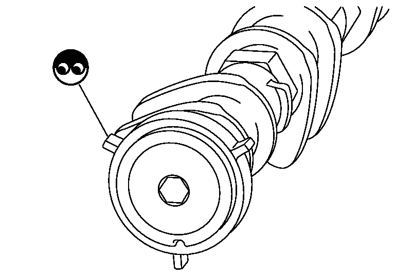
EXHAUST VALVE TIMING CONTROL POSITION SENSOR - 1
-
Turn ignition switch OFF.
-
Disconnect exhaust valve timing control position sensor harness connector.
-
Loosen the fixing bolt of the sensor.
-
Remove the sensor. Refer to Exploded View.
-
Visually check the sensor for chipping.

Is the inspection result normal?
YES>>GO TO 2.
NO>>Replace malfunctioning exhaust valve timing control position sensor. Refer to Exploded View.
EXHAUST VALVE TIMING CONTROL POSITION SENSOR - 2
Check resistance exhaust valve timing control position sensor terminals as follows.
| Exhaust valve timing control position sensor |
Condition | Resistance | ||
|---|---|---|---|---|
| + | − | |||
| Terminal | ||||
| 1 | 2 | Temperature | 25°C (77°F) | Except 0 Ω or ∞Ω |
| 1 | 3 | |||
| 2 | 3 | |||
Is the inspection result normal?
YES>>INSPECTION END
NO>>Replace malfunctioning exhaust valve timing control position sensor. Refer to Exploded View.
 P0850 Pnp Switch
DTC Description
DESCRIPTIONWhen the selector lever position is P or N, park/neutral position (PNP) signal from the transmission range switch is sent to ECM...
 P1148 Closed Loop Control
DTC Description
DTC DETECTION LOGIC DTC
CONSULT screen terms
(Trouble diagnosis content)
DTC detection condition
P1148
CLOSED LOOP-B1
(Closed loop bank 1)
Diagnosis condition
—
Signal (terminal)
—
Threshold
The closed loop control function for bank 1 does not operate even when Nissan Murano vehicle is being driven in the specified condition
Diagnosis delay time
—
P1168
CLOSED LOOP-B2
(Closed loop bank 2)
Diagnosis condition
—
Signal (terminal)
—
Threshold
The closed loop control function for bank 2 does not operate even when Nissan Murano vehicle is being driven in the specified condition
Diagnosis delay time
—
POSSIBLE CAUSE
Harness or connectors
(The A/F sensor 1 circuit is open or shorted...
Other information:
Nissan Murano (Z52) 2015-2024 Service Manual: U0428 Steering Angle Sensor
DTC Description DTC DETECTION LOGIC DTC No. CONSULT screen terms (Trouble diagnosis content) DTC detection condition U0428 ST ANGLE SENSOR CALIBRATION (Steering angle sensor calibration) Diagnosis condition When ignition switch is ON Signal (terminal) — Threshold — Diagnosis delay time — POSSIBLE CAUSE Neutral position adjustment of steering angle sensor is not complete Steering angle sensor FAIL-SAFE Predicted course line is not displayed MOD (Moving Object Detection) function is stopped DTC Confirmation Procedure CHECK DTC PRIORITY If DTC U0428 is displayed with DTC U1232, first perform the diagnosis for DTC U1232...
Nissan Murano (Z52) 2015-2024 Service Manual: System. Awd System
System Description SYSTEM DIAGRAMINPUT SIGNAL AND OUTPUT SIGNALIt transmits/receives each signal from the following AWD control unit via CAN communication line: Component parts Function ABS actuator and electric unit (control unit) Transmits the following signals via CAN communication to AWD control unit: Nissan Murano Vehicle speed signal Stop lamp switch signal (brake signal) Yaw rate sensor signal Side G sensor signal Decel G sensor signal ECM Transmits the following signals via CAN communication to AWD control unit: Accelerator pedal position signal Engine speed signal TCM Transmits the following signals via CAN communication to AWD control unit: Input shaft revolutional signal CVT ratio signal Combination meter Transmits conditions of parking brake switch signal via CAN communication to AWD control unit...
Categories
- Manuals Home
- Nissan Murano Owners Manual
- Nissan Murano Service Manual
- Warning lights
- System malfunction
- Passenger compartment
- New on site
- Most important about car
Driver and passenger supplemental knee air bag

Driver’s side
The knee air bag is located in the knee bolster, on the driver’s and passenger’s side. All of the information, cautions and warnings in this manual apply and must be followed. The knee air bag is designed to inflate in higher severity frontal collisions, although it may inflate if the forces in another type of collision are similar to those of a higher severity frontal impact. It may not inflate in certain collisions.

Passenger’s side