Nissan Murano: Interior Lighting System :: Dtc/circuit Diagnosis / Map Lamp Circuit
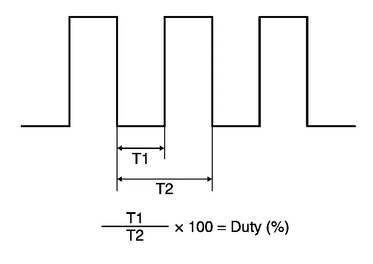
Controls the lamp (ground side) by PWM signal (duty) when the map lamp main switch is DOOR.
CAUTION:
Check the following items first:
-
Battery saver output/power supply circuit
-
Front room/map lamp assembly
CHECK MAP LAMP CONTROL FUNCTION
 CONSULT
-
Ignition switch ON.
-
Switch map lamp main switch DOOR.
-
Select “DR SEAT LAMP TEST” or “AS SEAT LAMP TEST” in “Active Test” mode of “BCM(INTELLIGENT KEY)”.
-
While operating the test items, check map lamps operation.
Test item Operation DR SEAT LAMP TEST On Map lamp
(driver side)ON Off OFF AS SEAT LAMP TEST On Map lamp
(passenger side)ON Off OFF
Are the map lamps turned ON/OFF?
YES>>Map lamp circuit is normal.
NO>>Refer to Diagnosis Procedure.
CHECK MAP LAMP CONTROL OUTPUT
CONSULT
-
Ignition switch ON.
-
Switch map lamp main switch DOOR.
-
Select “DR SEAT LAMP TEST” or “AS SEAT LAMP TEST” in “Active Test” mode of “BCM(INTELLIGENT KEY)”.
-
While operating the test items, check voltage between BCM harness connector and ground.
Driver side BCM — Test item Voltage
(Approx.)Connector Terminal M19 47 Ground DR SEAT LAMP TEST On 0 V Off Battery voltage Passenger side BCM — Test item Voltage
(Approx.)Connector Terminal M19 46 Ground AS SEAT LAMP TEST On 0 V Off Battery voltage
Is the inspection result normal?
Yes>>GO TO 2.
Fixed OFF>>Replace BCM. Refer to Removal and Installation.
Fixed ON>>GO TO 3.
CHECK MAP LAMP CONTROL CIRCUIT FOR OPEN
-
Ignition switch OFF.
-
Disconnect the BCM and front room/map lamp assembly connector.
-
Check continuity between the BCM harness connector and front room/map lamp assembly harness connector.
BCM Front room/map lamp assembly Continuity Connector Terminal Connector Terminal Driver side M19 47 R6 4 Yes Passenger side 46 5
Is the inspection result normal?
YES>>Replace the front room/map lamp assembly. Refer to Removal and Installation.
NO>>Repair the harnesses or connectors.
CHECK MAP LAMP CONTROL CIRCUIT FOR SHORT
-
Ignition switch OFF.
-
Disconnect the BCM and front room/map lamp assembly connector.
-
Check continuity between the BCM harness connector and ground.
BCM — Continuity Connector Terminal Driver side M19 47 Ground No Passenger side 46
Is the inspection result normal?
YES>>Replace BCM. Refer to Removal and Installation.
NO>>Repair the harnesses or connectors.
 Mood Lamp Circuit
Component Function Check
NOTE:
Before performing the diagnosis, check that the following are normal:
Battery saver output/power supply circuit
CHECK MOOD LAMP OPERATION
CONSULT
Ignition switch ON...
 Push-Button Ignition Switch Illumination Circuit
Component Function Check
CHECK PUSH-BUTTON IGNITION SWITCH ILLUMINATION OPERATION
CONSULT
Ignition switch ON.
Select “ENGINE SW ILLUMI” in “Active Test” mode of “BCM(INTELLIGENT KEY)”...
Other information:
Nissan Murano (Z52) 2015-2024 Service Manual: Normal Operating Condition
Description The following symptoms are normal operations, and they do not indicate a malfunction. Symptom Cause Action to take Reference page Entry/exit assist function does not operate. No initialization has been performed. Perform initialization...
Nissan Murano (Z52) 2015-2024 Owners Manual: Hood
Pull the hood lock release handle located below the driver side instrument panel until the hood springs up slightly. Locate the lever in between the hood and grille and push the lever sideways with your fingertips and raise the hood ...
Categories
- Manuals Home
- Nissan Murano Owners Manual
- Nissan Murano Service Manual
- Shift lock release
- Turning the AEB system on/off
- Rear bench seat adjustment
- New on site
- Most important about car
Luggage hooks

When securing items using luggage hooks located on the back of the seat or side finisher do not apply a load over more than 6.5 lbs. (29 N) to a single hook.
The luggage hooks that are located on the floor should have loads less than 110 lbs. (490 N) to a single hook.