
Nissan Murano: Interior Lighting System :: Dtc/circuit Diagnosis / Luggage Room Lamp
 NOTE:
Before performing the diagnosis, check that the following are normal:
-
Battery saver output/power supply circuit
-
Luggage room lamp bulb
CHECK LUGGAGE ROOM LAMP OPERATION
 CONSULT
-
Ignition switch ON.
-
Select “TRUNK/LUGGAGE LAMP TEST” in “Active Test” mode of “BCM(INTELLIGENT KEY)”.
-
While operating the test items, check that luggage room lamp turns ON/OFF.
On : Luggage room lamp ON Off : Luggage room lamp OFF
Does the luggage room lamp turn ON/OFF?
YES>>Luggage room lamp circuit is normal.
NO>>Refer to Diagnosis Procedure.
CHECK LUGGAGE ROOM LAMP OUTPUT
-
Ignition switch OFF.
-
Disconnect luggage room lamp connector.
-
Check continuity between BCM harness connector and ground.
| BCM | — | Condition | Continuity | ||
| Connector | Terminal | ||||
| M20 | 85 | Ground | Back door | Open | Yes |
| Closed | No | ||||
Is the inspection result normal?
YES>>GO TO 2.
NO>>Continuity exists and remains unchanged: GO TO 3.
NO>>Continuity does not exist and remains unchanged: Replace BCM. Refer to Removal and Installation.
CHECK LUGGAGE ROOM LAMP OPEN CIRCUIT
-
Disconnect BCM connector.
-
Check continuity between BCM harness connector and luggage room lamp harness connector.
BCM Luggage room lamp Continuity Connector Terminal Connector Terminal M20 85 B26 2 Yes
Is the inspection result normal?
YES>>Replace luggage room lamp. Refer to Removal and Installation.
NO>>Repair or replace harnesses.
CHECK LUGGAGE ROOM LAMP SHORT CIRCUIT
-
Disconnect BCM connector.
-
Check continuity between BCM harness connector and ground.
BCM — Continuity Connector Terminal M20 85 Ground No
Is the inspection result normal?
YES>>Replace BCM. Refer to Removal and Installation.
NO>>Repair or replace harnesses.
 Interior Room Lamp Control Circuit
Component Function Check
CAUTION:
Before performing the diagnosis, check that the following are normal:
Battery saver output/power supply circuit
Front room/map lamp assembly
Personal lamps 2nd row
CHECK INTERIOR ROOM LAMP CONTROL FUNCTION
CONSULT
Set the front room/map lamp assembly switch and personal lamps 2nd row switch to DOOR:
Ignition switch ON...
 Mood Lamp Circuit
Component Function Check
NOTE:
Before performing the diagnosis, check that the following are normal:
Battery saver output/power supply circuit
CHECK MOOD LAMP OPERATION
CONSULT
Ignition switch ON...
Other information:
Nissan Murano (Z52) 2015-2024 Service Manual: B2724 Sonar Control Unit
DTC Description DTC DETECTION LOGIC DTC No. CONSULT screen terms (Trouble diagnosis content) DTC detection condition B2724–23 SONAR CONTROL UNIT (Sonar control unit) — Diagnosis condition When ignition switch is ON Signal (terminal) — Threshold Sonar ECU internal failure (under voltage) Diagnosis delay time — B2724–24 Diagnosis condition When ignition switch is ON Signal (terminal) — Threshold Sonar ECU internal failure (over voltage) Diagnosis delay time — B2724–44 Diagnosis condition When ignition switch is ON Signal (terminal) — Threshold Sonar ECU internal failure (RAM failure) Diagnosis delay time — B2724–45 Diagnosis condition When ignition switch is ON Signal (terminal) — Threshold Sonar ECU internal failure (ROM failure) Diagnosis delay time — B2724–46 Diagnosis condition When ignition switch is ON Signal (terminal) — Threshold Sonar ECU internal failure (EEPROM failure) Diagnosis delay time — B2724–48 Diagnosis condition When ignition switch is ON Signal (terminal) — Threshold Sonar ECU internal failure (internal software execution failure) Diagnosis delay time — B2724–49 Diagnosis condition When ignition switch is ON Signal (terminal) — Threshold Sonar ECU internal failure (basic chip set failure) Diagnosis delay time — B2724–55 Diagnosis condition When ignition switch is ON Signal (terminal) — Threshold Sonar ECU internal failure (not configured) Diagnosis delay time — B2724–86 Diagnosis condition When ignition switch is ON Signal (terminal) — Threshold Sonar ECU internal failure (SPI comm failure) Diagnosis delay time — B2724–87 Diagnosis condition When ignition switch is ON Signal (terminal) — Threshold Sonar ECU internal failure (high side switch failure) Diagnosis delay time — POSSIBLE CAUSE Charging system malfunction Sonar control unit power supply or ground circuit Sonar control unit configuration Sonar control unit FAIL-SAFE Off indicator blinks periodically (500ms ON, 500ms OFF)...
Nissan Murano (Z52) 2015-2024 Service Manual: P0196 Eot Sensor
DTC Description DTC DETECTION LOGIC Rationally incorrect voltage from the sensor is sent to ECM, compared with the voltage signals from EOT sensor and intake air temperature sensor. The comparison result of signals transmitted to ECM from each temperature sensor (IAT sensor, ECT sensor, FTT sensor, and EOT sensor) shows that the signal voltage of the EOT sensor is higher/lower than that of other temperature sensors when the engine is started with its cold state...
Categories
- Manuals Home
- Nissan Murano Owners Manual
- Nissan Murano Service Manual
- Tire rotation
- Shift lock release
- Settings
- New on site
- Most important about car
Seatback pockets
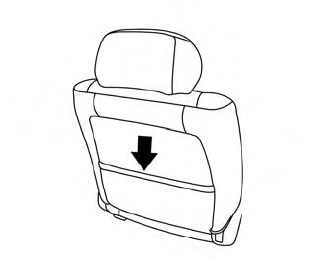
Theremaybe one or two seatback pockets located on the back of the driver and passenger seats. The pockets can be used to store maps.
WARNING
