Nissan Murano: Instruments and controls / Heated seat switches (if so equipped)
Nissan Murano (Z52) 2015-2024 Owners Manual / Instruments and controls / Heated seat switches (if so equipped)
WARNING
Do not use or allow occupants to use the seat heater if you or the occupants cannot monitor elevated seat temperatures or have an inability to feel pain in those body parts in contact with the seat. Use of the seat heater by such people could result in serious injury.
CAUTION
- The battery could run down if the seat heater is operated while the engine is not running.
- Do not use the seat heater for extended periods or when no one is using the seat.
- Do not put anything on the seat which insulates heat, such as a blanket, cushion, seat cover, etc. Otherwise, the seat may become overheated.
- Do not place anything hard or heavy on the seat or pierce it with a pin or similar object. Thismayresult in damage to the heater.
- Any liquid spilled on the heated seat should be removed immediately with a dry cloth.
- When cleaning the seat, never use gasoline, benzine, thinner, or any similar materials.
- If any malfunctions are found or the heated seat does not operate, turn the switch off and have the system checked. It is recommended that you visit a NISSAN dealer for this service.

The front seats are warmed by built-in heaters.
- Start the engine.
- Push the LOor HI position of the switch,
as desired. The indicator light in the
switch will illuminate.
The heater is controlled by a thermostat, automatically turning the heater on and off. The indicator light will remain on as long as the switch is on.
- When the seat is warmed or before you leave the vehicle, be sure to push the switch to turn it off.
 Climate controlled seat switches (if so equipped)
The climate controlled seat warms up or
cools down the front seat by blowingwarm
or cool air from under the surface of the
seat. The climate control switch is located
on the center console...
 Heated rear seat switches (if so equipped)
WARNING
Do not use or allow occupants to use
the seat heater if you or the occupants
cannot monitor elevated seat temperatures
or have an inability to feel pain in
body parts that contact the seat...
Other information:
Nissan Murano (Z52) 2015-2024 Owners Manual: Vehicle information display
The vehicle information display is located to the left of the speedometer. It displays such items as: Home Audio information Navigation information (if so equipped) Drive computer information Fuel economy information Driving aids information (if so equipped) Speed Limit Sign (if so equipped) Tire pressure information Indicators and warnings Vehicle and meter display settings Cruise control status Odometer/twin trip odometer Gear position information (P, R, N, D) Distance To Empty and fuel indicator Time Outside Air Temperature The display will be interrupted when a phone call is received...
Nissan Murano (Z52) 2015-2024 Service Manual: B2724 Sonar Control Unit
DTC Description DTC DETECTION LOGIC DTC No. CONSULT screen terms (Trouble diagnosis content) DTC detection condition B2724–23 SONAR CONTROL UNIT (Sonar control unit) — Diagnosis condition When ignition switch is ON Signal (terminal) — Threshold Sonar ECU internal failure (under voltage) Diagnosis delay time — B2724–24 Diagnosis condition When ignition switch is ON Signal (terminal) — Threshold Sonar ECU internal failure (over voltage) Diagnosis delay time — B2724–44 Diagnosis condition When ignition switch is ON Signal (terminal) — Threshold Sonar ECU internal failure (RAM failure) Diagnosis delay time — B2724–45 Diagnosis condition When ignition switch is ON Signal (terminal) — Threshold Sonar ECU internal failure (ROM failure) Diagnosis delay time — B2724–46 Diagnosis condition When ignition switch is ON Signal (terminal) — Threshold Sonar ECU internal failure (EEPROM failure) Diagnosis delay time — B2724–48 Diagnosis condition When ignition switch is ON Signal (terminal) — Threshold Sonar ECU internal failure (internal software execution failure) Diagnosis delay time — B2724–49 Diagnosis condition When ignition switch is ON Signal (terminal) — Threshold Sonar ECU internal failure (basic chip set failure) Diagnosis delay time — B2724–55 Diagnosis condition When ignition switch is ON Signal (terminal) — Threshold Sonar ECU internal failure (not configured) Diagnosis delay time — B2724–86 Diagnosis condition When ignition switch is ON Signal (terminal) — Threshold Sonar ECU internal failure (SPI comm failure) Diagnosis delay time — B2724–87 Diagnosis condition When ignition switch is ON Signal (terminal) — Threshold Sonar ECU internal failure (high side switch failure) Diagnosis delay time — POSSIBLE CAUSE Charging system malfunction Sonar control unit power supply or ground circuit Sonar control unit configuration Sonar control unit FAIL-SAFE Off indicator blinks periodically (500ms ON, 500ms OFF)...
Categories
- Manuals Home
- Nissan Murano Owners Manual
- Nissan Murano Service Manual
- Intelligent Forward Collision Warning (I-FCW)
- Indicator lights
- How to enable/disable the LDW system
- New on site
- Most important about car
Fuel gauge
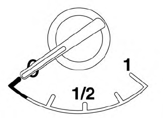
The gauge indicates the approximate fuel level in the tank.
The gauge may move slightly during braking, turning, acceleration, or going up or down hills.
The gauge needle returns to 0 (Empty) after the ignition switch is placed in the OFF position.

Copyright © 2026 www.nimurano.com