
Nissan Murano: Sonar System :: Dtc/circuit Diagnosis / B2724 Sonar Control Unit
DTC DETECTION LOGIC
| DTC No. |
CONSULT screen terms (Trouble diagnosis content) | DTC detection condition | ||
|---|---|---|---|---|
| B2724–23 |
SONAR CONTROL UNIT (Sonar control unit) |
— | Diagnosis condition | When ignition switch is ON |
| Signal (terminal) | — | |||
| Threshold | Sonar ECU internal failure (under voltage) | |||
| Diagnosis delay time | — | |||
| B2724–24 | Diagnosis condition | When ignition switch is ON | ||
| Signal (terminal) | — | |||
| Threshold | Sonar ECU internal failure (over voltage) | |||
| Diagnosis delay time | — | |||
| B2724–44 | Diagnosis condition | When ignition switch is ON | ||
| Signal (terminal) | — | |||
| Threshold | Sonar ECU internal failure (RAM failure) | |||
| Diagnosis delay time | — | |||
| B2724–45 | Diagnosis condition | When ignition switch is ON | ||
| Signal (terminal) | — | |||
| Threshold | Sonar ECU internal failure (ROM failure) | |||
| Diagnosis delay time | — | |||
| B2724–46 | Diagnosis condition | When ignition switch is ON | ||
| Signal (terminal) | — | |||
| Threshold | Sonar ECU internal failure (EEPROM failure) | |||
| Diagnosis delay time | — | |||
| B2724–48 | Diagnosis condition | When ignition switch is ON | ||
| Signal (terminal) | — | |||
| Threshold | Sonar ECU internal failure (internal software execution failure) | |||
| Diagnosis delay time | — | |||
| B2724–49 | Diagnosis condition | When ignition switch is ON | ||
| Signal (terminal) | — | |||
| Threshold | Sonar ECU internal failure (basic chip set failure) | |||
| Diagnosis delay time | — | |||
| B2724–55 | Diagnosis condition | When ignition switch is ON | ||
| Signal (terminal) | — | |||
| Threshold | Sonar ECU internal failure (not configured) | |||
| Diagnosis delay time | — | |||
| B2724–86 | Diagnosis condition | When ignition switch is ON | ||
| Signal (terminal) | — | |||
| Threshold | Sonar ECU internal failure (SPI comm failure) | |||
| Diagnosis delay time | — | |||
| B2724–87 | Diagnosis condition | When ignition switch is ON | ||
| Signal (terminal) | — | |||
| Threshold | Sonar ECU internal failure (high side switch failure) | |||
| Diagnosis delay time | — | |||
POSSIBLE CAUSE
-
Charging system malfunction
-
Sonar control unit power supply or ground circuit
-
Sonar control unit configuration
-
Sonar control unit
FAIL-SAFE
-
Off indicator blinks periodically (500ms ON, 500ms OFF).
-
Sonar buzzer sounds for 3 seconds.
DTC CONFIRMATION PROCEDURE
 CONSULT
-
Ignition switch ON.
-
Select “Self Diagnostic Result” mode of “SONAR”.
Is DTC B2724–23, 24, 44, 45, 46, 48, 49, 55, 86, 87 detected?
YES>>Refer to DTC Diagnosis Procedure.
NO>>To check malfunction symptom before repair: Refer to Intermittent Incident.
NO>>Confirmation after repair: Inspection End.
DETERMINE MALFUNCTION TYPE
CONSULT
-
Ignition switch ON.
-
Select “Self Diagnostic Result” mode of “SONAR”.
-
Check DTC.
Is DTC B2724–23, 24, 44, 45, 46, 48, 49, 55, 86 or 87 detected?
YES>>23 or 24 – GO TO 2.
YES>>55 – GO TO 4.
YES>>44, 45, 46, 48, 49, 86 or 87 – GO TO 5.
NO>>Refer to Intermittent Incident.
CHECK CHARGING SYSTEM
Check the Nissan Murano vehicle charging system. Refer to Work Flow (With 165-DSS-5000P) or Work Flow (Without 165-DSS-5000P).
Is the inspection result normal?
YES>>GO TO 3.
NO>>Repair or replace the malfunctioning components.
CHECK SONAR CONTROL UNIT POWER SUPPLY AND GROUND
Perform the sonar control unit power supply and ground circuit diagnosis procedure. Refer to Diagnosis Procedure.
Is the inspection result normal?
YES>>Replace sonar control unit. Refer to Removal and Installation.
NO>>Repair or replace harness or connectors.
PERFORM SONAR CONTROL UNIT CONFIGURATION PROCEDURE
CONSULT
Perform the sonar control unit configuration procedure. Refer to Work Procedure.
Was the configuration procedure successful?
YES>>GO TO 5.
NO>>Replace sonar control unit. Refer to Removal and Installation.
PERFORM DTC CONFIRMATION PROCEDURE AGAIN
CONSULT
-
Ignition switch ON.
-
Erase DTC.
-
Select “Self Diagnostic Result” mode of “SONAR”.
-
Check DTC.
Is DTC B2724–44, 45, 46, 48, 49, 55, 86 or 87 detected?
YES>>Replace sonar control unit. Refer to Removal and Installation.
NO>>Inspection End.
 B2720 Corner Sensor [rl]
DTC Description
DTC DETECTION LOGIC DTC No.
CONSULT screen terms
(Trouble diagnosis content)
DTC detection condition
B2720–60
CORNER SENSOR [RL]
(Rear sonar sensor LH outer)
—
Diagnosis condition
When ignition switch is ON
Signal (terminal)
—
Threshold
Rear sonar sensor LH outer internal failure (reset error)
Diagnosis delay time
—
B2720–61
Diagnosis condition
When ignition switch is ON
Signal (terminal)
—
Threshold
Rear sonar sensor LH outer internal failure (configuration error)
Diagnosis delay time
—
B2720–62
Diagnosis condition
When ignition switch is ON
Signal (terminal)
—
Threshold
Rear sonar sensor LH outer internal failure (power supply error)
Diagnosis delay time
—
B2720–63
Diagnosis condition
When ignition switch is ON
Signal (terminal)
—
Threshold
Rear sonar sensor LH outer internal failure (self diag result)
Diagnosis delay time
—
B2720–65
Diagnosis condition
When ignition switch is ON
Signal (terminal)
—
Threshold
Rear sonar sensor LH outer internal failure (over temperature)
Diagnosis delay time
—
B2720–66
Diagnosis condition
When ignition switch is ON
Signal (terminal)
Rear sonar sensor LH outer signal (terminal 22)
Threshold
Rear sonar sensor LH outer signal circuit is open or short to ground
Diagnosis delay time
—
B2720–67
Diagnosis condition
When ignition switch is ON
Signal (terminal)
—
Threshold
Rear sonar sensor LH outer internal failure (diag dump error)
Diagnosis delay time
—
B2720–68
Diagnosis condition
When ignition switch is ON
Signal (terminal)
—
Threshold
Rear sonar sensor LH outer internal failure (resonator error)
Diagnosis delay time
—
B2720–83
Diagnosis condition
When ignition switch is ON
Signal (terminal)
—
Threshold
Rear sonar sensor LH outer internal failure (CRC error)
Diagnosis delay time
—
B2720–92
Diagnosis condition
When ignition switch is ON
Signal (terminal)
—
Threshold
Rear sonar sensor LH outer internal failure (membrane error)
Diagnosis delay time
—
POSSIBLE CAUSE
Harness or connectors
Rear sonar sensor LH outer
FAIL-SAFE
Obstacle detection of rear sonar sensor LH outer is stopped
Audible warning (sonar buzzer) of all sensors is stopped
Sonar buzzer sounds for 3 seconds
DTC Confirmation Procedure
DTC CONFIRMATION PROCEDURE
CONSULT
Ignition switch ON...
 B272d Front Buzzer
DTC Description
DTC DETECTION LOGIC DTC No.
CONSULT screen terms
(Trouble diagnosis content)
DTC detection condition
B272D–12
FRONT BUZZER
(Sonar buzzer)
—
Diagnosis condition
When ignition switch is ON
Signal (terminal)
Sonar buzzer power circuit (terminal 19)
Sonar buzzer signal (terminal 18)
Threshold
Sonar buzzer power circuit is short to voltage
Sonar buzzer signal circuit is short to voltage
Diagnosis delay time
—
B272D–14
Diagnosis condition
When ignition switch is ON
Signal (terminal)
Sonar buzzer power circuit (terminal 19)
Sonar buzzer signal (terminal 18)
Threshold
Sonar buzzer power circuit is open or short to ground
Sonar buzzer signal circuit is open or short to ground
Diagnosis delay time
—
POSSIBLE CAUSE
Harness or connectors
Sonar buzzer
FAIL-SAFE
Off indicator blinks periodically (500ms ON, 500ms OFF)...
Other information:
Nissan Murano (Z52) 2015-2024 Service Manual: P0965 Pressure Control Solenoid B
DTC Description DTC DETECTION LOGIC DTC CONSULT screen terms (Trouble diagnosis content) DTC detection condition P0965 PC SOLENOID B (Pressure Control Solenoid B Control Circuit Range Performance) 1 Diagnosis condition When all of the following conditions are satisfied: DTC other than the applicable DTC is not detected...
Nissan Murano (Z52) 2015-2024 Service Manual: Bcm (body Control Module)
L..
Categories
- Manuals Home
- Nissan Murano Owners Manual
- Nissan Murano Service Manual
- Rear bench seat adjustment
- Jacking up vehicle and removing the damaged tire
- Turning the AEB system on/off
- New on site
- Most important about car
Vehicle security system
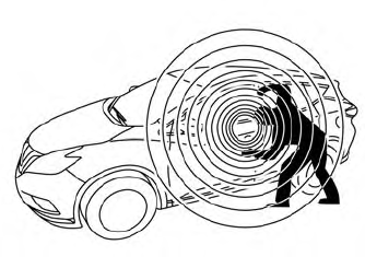
Your vehicle has two types of security systems:
Vehicle security system NISSAN Vehicle Immobilizer SystemThe vehicle security system provides visual and audible alarm signals if someone opens the doors, liftgate or the hood when the system is armed. It is not, however, a motion detection type system that activates when a vehicle is moved or when a vibration occurs.
