Nissan Murano: Transmission Assembly / Front Wheel Drive
Removal
WARNING:
Do not remove the radiator cap when the engine is hot. Serious burns could occur from high pressure engine coolant escaping from the radiator. Wrap a thick cloth around the cap. Slowly turn it a quarter turn to allow built-up pressure to escape. Carefully remove the cap by turning it all the way.
CAUTION:
-
Perform when the engine is cold.
-
When replacing the TCM and transaxle assembly as a set, replace the transaxle assembly first and then replace the TCM. Refer to Description.
-
When replacing the transaxle assembly, perform "ADDITIONAL SERVICE WHEN REPLACING TRANSAXLE ASSEMBLY." Refer to Description.
 NOTE:
NOTE:
When removing components such as hoses, tubes/lines, etc., cap or plug openings to prevent fluid from spilling.
Remove starter. Refer to Removal and Installation.
Remove the cowl top cover and the cowl top extension. Refer to cowl top cover Removal and Installation and cowl top extension Removal and Installation - Cowl Top Extension.
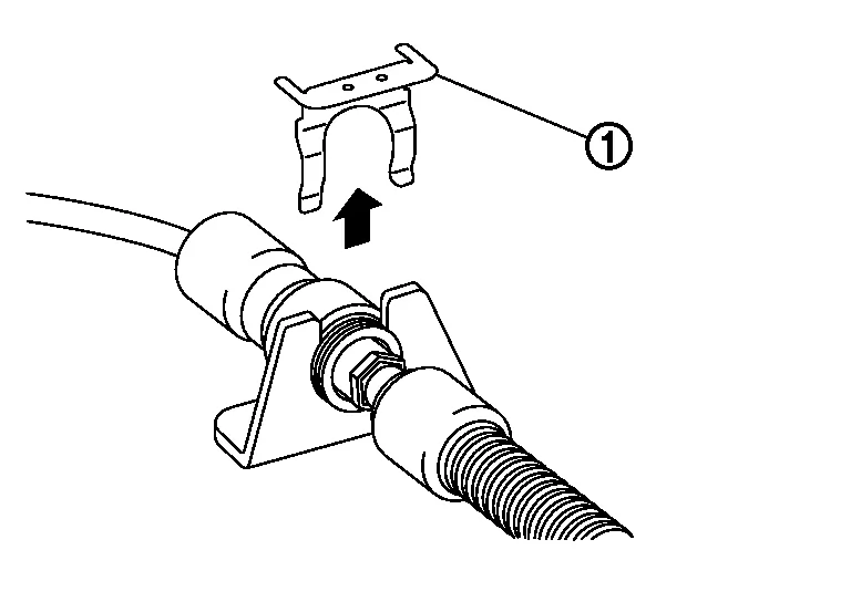
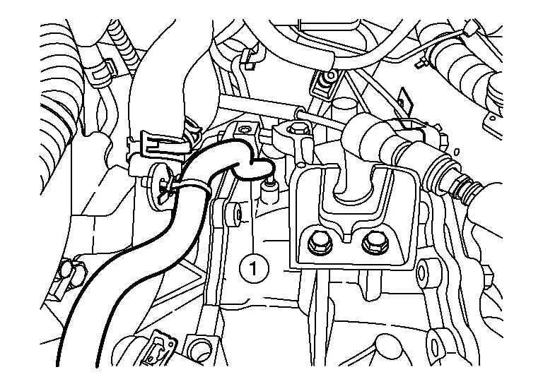
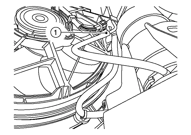
Remove lock plate (1) as shown.
Remove nut (A) and separate control cable (1) from the manual lever (B).
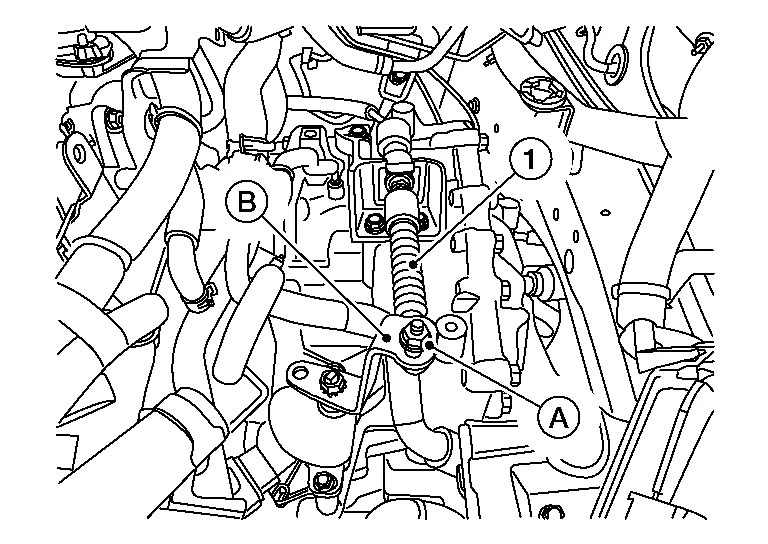
Disconnect the harness connector (A) from the transmission range switch (1).

Disconnect brake booster vacuum hose from intake manifold collector. Refer to Exploded View.
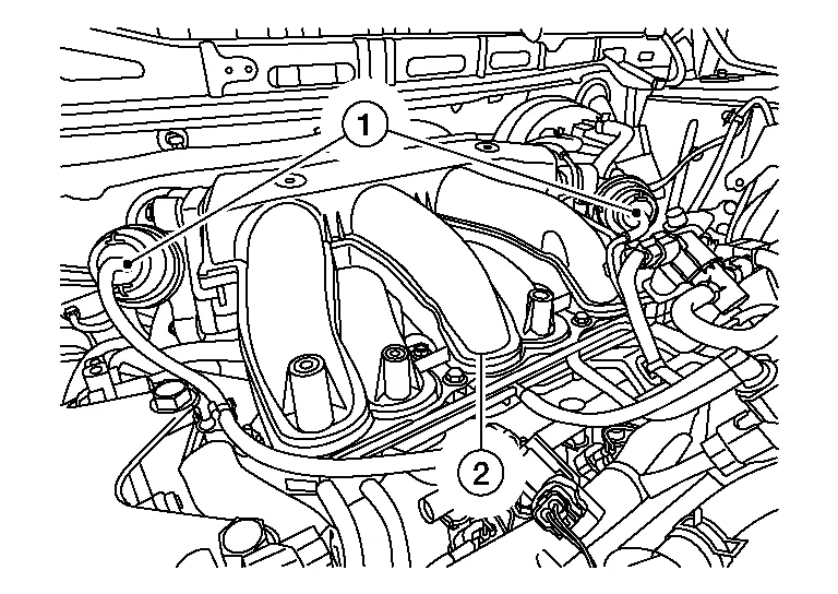
Release clamp and disconnect PCV hose (1) from intake manifold collector (2).

Remove bolts (A) and set VIAS control solenoid valves (1) aside.

Disconnect vacuum hoses (1) from intake manifold collector (2).
Disconnect vacuum hose (1) from vacuum pipe (2).

Remove bolt (A).
Remove clamp (1) and disconnect hose (2) from pipe (3).
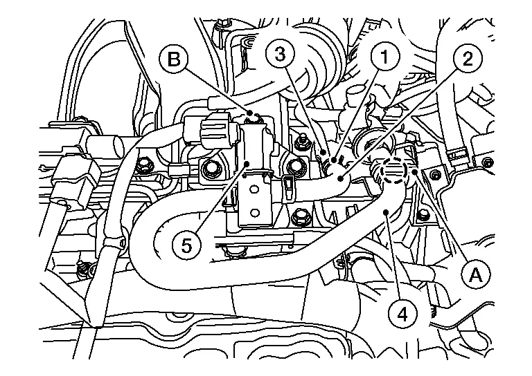
Release pawl and remove hose (4) from retainer (A).
 |
: Pawl |
Remove bolt (B) and set EVAP canister purge volume control solenoid (5) aside.
Remove bolts (A) and set vacuum tube assembly (1) aside.

Loosen bolts in reverse of sequence shown and remove electric throttle control actuator bolts, then remove electric throttle control actuator and position aside.

CAUTION:
-
Handle carefully to avoid any shock to the electric throttle control actuator.
-
Do not disassemble electric throttle control actuator.
Remove bolt (A) and set O2 sensor harness bracket (1) aside.

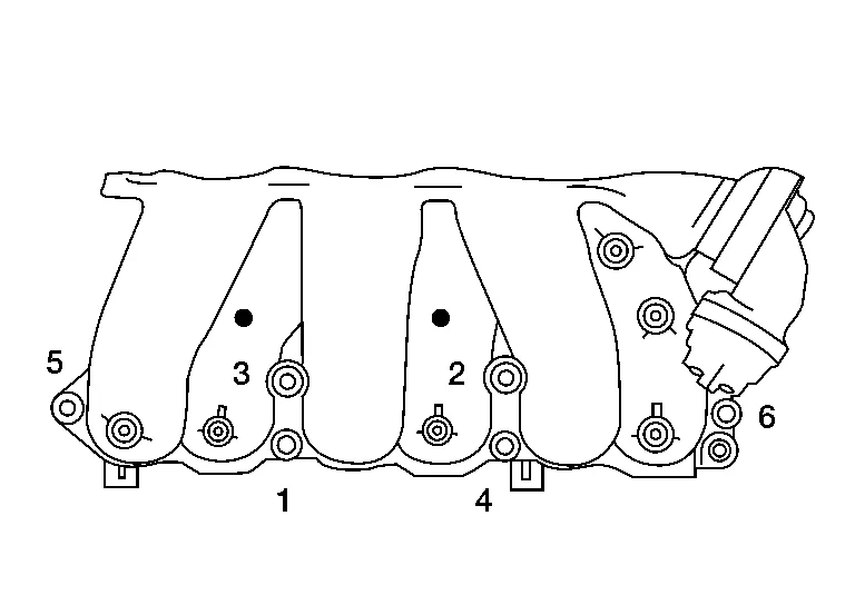
Loosen the intake manifold collector bolts and nuts in reverse of the sequence shown, then remove the intake manifold collector and gasket.
CAUTION:
Do not reuse intake manifold collector gasket.
Disconnect transaxle breather hose (1) from transaxle assembly.
Remove bolt (A) from upper torque rod.

Remove fuel tube bolts (A).

Remove CVT gusset bolt (A).

Remove bolts (A).

Remove nuts (A) and bracket (1).

Install Tool (B) using bolts (A) and (C) supplied with Tool. Tighten bolts to specification. Refer to Engine Support Tool Operating Instructions.
| Tool (B) | : (J-52604) |
| Bolts (A) | : 20 N·m (2.0 kg-m, 15 ft-lb) |
| Bolts (C) | : 11 N·m (1.1 kg-m, 8 ft-lb) |

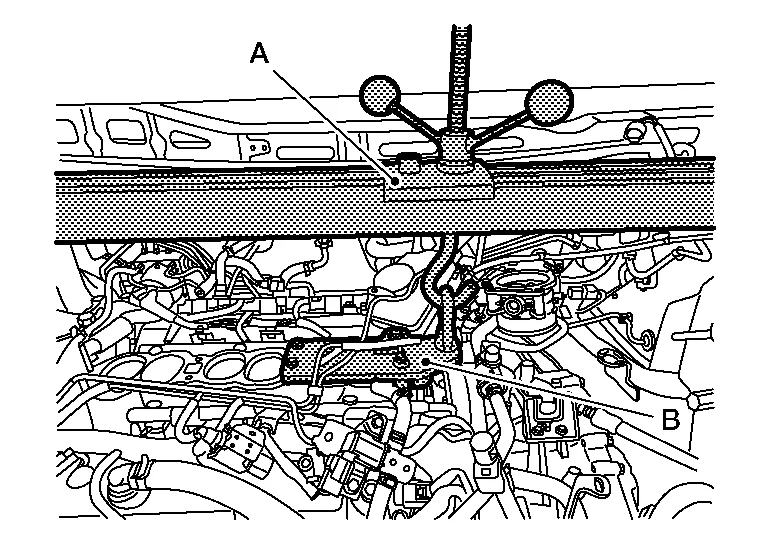
Install Tool (A) to drivers side frame rail (1) as shown. Refer to Engine Support Tool Operating Instructions.

| Tool (A) | : (J-52389) |
Install Tool (A) on top of engine mounting insulator [RH (1)] as shown. Refer to Engine Support Tool Operating Instructions.
| Tool (A) | : (J-52389) |
Install Tool (A) to Tool (B). Refer to Engine Support Tool Operating Instructions.
| Tool (A) | : (J-52389) |
| Tool (B) | : (J-52604) |
Using bubble level (B) on Tool (A) level Tool as shown. Refer to Engine Support Tool Operating Instructions.

| Tool (A) | : (J-52389) |
Remove nut from engine mounting insulator (front). Refer to Exploded View.
Remove nut from engine mounting insulator (rear). Refer to Exploded View.
Remove the front wheels and tires using power tool (LH/RH).
Remove brake hose retaining clip and brake hose from strut (LH/RH).
Remove brake caliper torque member bolts using power tool, leaving hydraulic hose attached to the brake caliper. Position the brake caliper aside with wire (LH/RH). Refer to Exploded View.
CAUTION:
-
Do not twist or stretch the brake hose.
-
Do not depress brake pedal while brake caliper is removed.
Put alignment marks (A) on the disc brake rotor and on the wheel hub and bearing, then remove disc brake rotor (LH/RH).

CAUTION:
Do not drop the disc brake rotors.
Remove wheel sensor bolt (A) and position wheel sensor aside (LH/RH).

CAUTION:
Do not pull on wheel sensor harness.
Remove and discard cotter pin from front drive shaft (LH/RH).
CAUTION:
Do not reuse cotter pins.
Remove nut retainer from drive shaft (LH/RH).
Loosen the wheel hub lock nut from the drive shaft using power tool (LH/RH).
CAUTION:
Do not reuse wheel hub lock nuts.
Remove front strut to steering knuckle bolts and nuts, then separate front strut from steering knuckle (LH/RH). Refer to Exploded View.
Using a piece of wood and a suitable tool, tap on the wheel hub lock nut to disengage the drive shaft from the wheel hub and bearing (LH/RH).

CAUTION:
-
Do not place drive shaft joints at an extreme angle. Be careful not to over extend slide joints.
-
Do not allow drive shafts to hang without support.
NOTE:
Use suitable puller if drive shafts cannot be separated from wheel hub and bearings.
Remove the wheel hub lock nut (LH/RH).
CAUTION:
Do not reuse wheel hub lock nuts.
Remove bearing retainer to support bearing bracket bolts and remove bearing retainer (RH only).
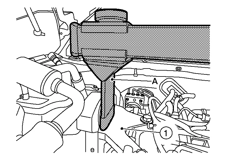
Insert suitable tool (A) between the drive shaft and transaxle. Remove the drive shaft from the transaxle (LH/RH).
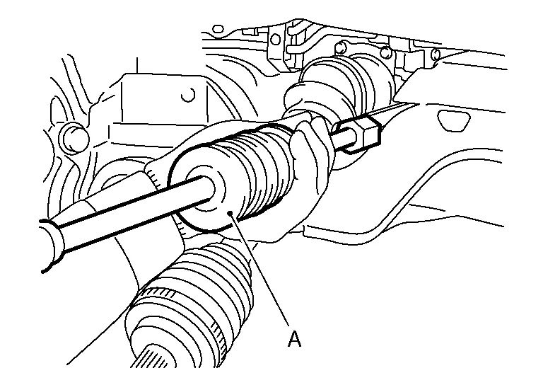
CAUTION:
-
Confirm that the circular clips are attached to the drive shafts.
-
Do not place drive shaft joints at extreme angles when removing drive shafts. Also be careful not to overextend slide joints.
-
Do not reuse circular clips.
| Tool (A) | : Drive shaft joint puller (Commercially available) |
Remove the differential side oil seal (LH/RH).
CAUTION:
Do not reuse differential side oil seals.
Remove nut and separate stabilizer connecting rods from struts (LH/RH). Refer to Exploded View.
Remove outer socket cotter pins (LH/RH). Refer to Exploded View.
CAUTION:
Do not reuse outer socket cotter pins.
Loosen the outer socket nuts and separate outer sockets from the steering knuckles (LH/RH) using ball joint remover (commercially available).
CAUTION:
Leave the outer socket nuts half threaded on the outer sockets to prevent damage to threads and to prevent the tool from coming off suddenly.
Remove the outer socket nuts and separate the outer sockets from the steering knuckles (LH/RH).
Remove front under cover. Refer to Exploded View.
Remove the front half of front over fenders (LH/RH). Refer to Exploded View.
Remove engine side cover (LH/RH). Refer to Exploded View.
Remove the front half of front fender protectors (LH/RH). Refer to Exploded View.
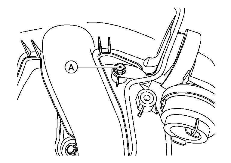
Remove bolt (A) and position crankshaft position sensor (1) aside.

Remove the front exhaust tube. Refer to Exploded View.
Disconnect the front engine mount insulator vacuum hose (1).
Remove bolt (A) and remove rear cover plate (1).

Remove torque converter nuts. Refer to Exploded View.
Remove the power steering tube bracket bolts. Refer to Exploded View.
Remove the bolts and nuts from the steering gear. Refer to Exploded View.
Secure the steering gear using suitable wire.
CAUTION:
The steering gear will remain in Nissan Murano vehicle. Secure steering gear using suitable wire.
Remove bolts (A) from transaxle mount.

Remove bolt (A) and position ground (1) aside.

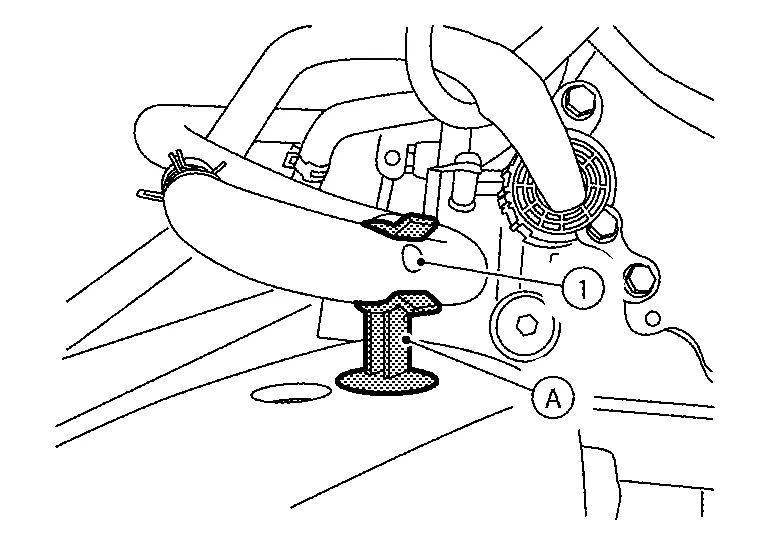
Remove water hose (1) from retainer (A).
Remove rear torque rod bolt. Refer to Exploded View.
Set hydraulic lift table (A) or equivalent tool under front suspension member.

Remove front suspension member bolts and front suspension member stays. Refer to Exploded View.
CAUTION:
Secure front suspension member to hydraulic lift table (or equivalent tool) while removing it.
Lower the front suspension member.
Remove bolt from heater thermostat bracket. Refer to Exploded View.
Drain engine coolant. Refer to Changing Engine Coolant.
Remove CVT fluid cooler hose A and CVT fluid cooler hose B from the CVT oil warmer. Refer to Exploded View.
Remove CVT water hose A and CVT water hose B from CVT oil warmer. Refer to Exploded View.
Using Tools lower engine and transaxle assembly until the transaxle assembly is low enough to clear driver’s side frame rail.
| Tool numbers | : (J-52389, J-52604) |
Release the harness retainers from the transaxle assembly.
Disconnect the harness connector (A) from the transaxle assembly.

Disconnect the harness connector from the output speed sensor. Refer to Exploded View.
Disconnect the harness connector from the primary speed sensor. Refer to Exploded View.
Disconnect the harness connector from the input speed sensor. Refer to Exploded View.
Support transaxle assembly using a suitable transmission jack and Tool.
| Tool number | : (J-51307) |
CAUTION:
-
Always secure transaxle assembly to transmission jack.
-
Do not lift or support transaxle assembly using the bottom of oil pan or damage can occur.
Remove bolts (A), (B), (C), and (D).
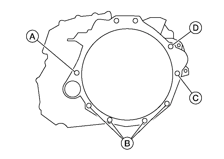
Separate the transaxle assembly from the engine assembly and lower transaxle assembly.
CAUTION:
Secure the torque converter to the transaxle while removing transaxle to prevent torque converter from falling.
INSTALLATION
Installation is in the reverse order of removal.
If replacing CVT, flush the CVT fluid cooler and lines. Refer to CVT Fluid Cooler Flush.
Perform inspection before installation. Refer to "Inspection Before Installation" below.
NOTE:
-
If the same transaxle assembly will be reinstalled, replace differential side oil seals (LH/RH). Refer to Exploded View.
-
If a new transaxle assembly is being installed, write down the serial number of the new transaxle assembly.

CAUTION:
-
When replacing an engine or transaxle you must make sure any dowels are installed correctly during re-assembly
-
Improper alignment caused by missing dowels may cause vibration, oil leaks or breakage of drivetrain components.
-
Do not reuse O-rings or copper sealing washers.
-
When turning crankshaft, turn it clockwise as viewed from the front of the engine.
-
When tightening the nuts for the torque converter while securing the crankshaft pulley bolt, be sure to confirm the tightening torque of the crankshaft pulley bolt. Refer to Removal and Installation.
-
After torque converter is installed to drive plate, rotate crankshaft several turns to check that CVT rotates freely without binding.
-
When installing the CVT to the engine, align the matching mark on the drive plate with the matching mark on the torque converter.
-
Do not reuse differential side oil seals.
-
When installing the CVT to the engine, align the matching mark on the drive plate with the matching mark on the torque converter.
NOTE:
-
When installing the drive plate to torque converter nuts, tighten them temporarily. then tighten the nuts to the specified torque. Refer to Exploded View.
-
Install the transaxle assembly and engine assembly mounting bolts according to the following standards.
Bolt No. 1 2 3 4 5 Number of bolts 1 2 1 1 4 Bolt length
“ ”mm (in)
 52 (2.05) 47 (1.85) 36 (1.42) 32 (1.26) 29 (1.14) 32 (1.26) 44 (1.73) 47 (1.85) 45 (1.77) Tightening torque
N·m (kg-m, ft-lb)74.5 (7.6, 55) 62 (6.3, 46) 74.5 (7.6, 55) 62 (6.3, 46) 74.5 (7.6, 55) 62 (6.3, 46) 74.5 (7.6, 55) 62 (6.3, 46) 50.0 (5.1, 37) 
-
Perform adjustment after installation. Refer to Adjustment after Installation.
-
Perform inspection after installation. Refer to Inspection after Installation.
 Transmission Assembly
Exploded View
FWD Models 1.
Gusset
2.
Transaxle assembly
3.
O-ring
4.
CVT fluid charging pipe
5.
Water outlet
6.
CVT fluid charging pipe cap
A...
 All Wheel Drive
Removal and Installation - AWD
RemovalWARNING:
Do not remove the radiator cap when the engine is hot. Serious burns could occur from high pressure engine coolant escaping from the radiator...
Other information:
Nissan Murano (Z52) 2015-2024 Service Manual: Driver Seat Control Unit
Removal and Installation REMOVALRemove the driver seat. Refer to Removal and Installation. Remove the two driver seat control unit (1) screws (A). : Front Disconnect the two harness connectors from driver seat control unit. Remove driver seat control unit...
Nissan Murano (Z52) 2015-2024 Service Manual: B2196 Dongle Ng
DTC Description BCM performs ID verification between BCM and dongle unit.When verification result is OK, BCM permits cranking.DTC DETECTION LOGICNOTE: If DTC B2196 is displayed with DTC U1000, first perform the trouble diagnosis for DTC U1000. Refer to DTC Description...
Categories
- Manuals Home
- Nissan Murano Owners Manual
- Nissan Murano Service Manual
- Jacking up vehicle and removing the damaged tire
- Intelligent Forward Collision Warning (I-FCW)
- All-Wheel Drive (AWD) (if so equipped)
- New on site
- Most important about car