Nissan Murano: Interior :: Removal and Installation / Headlining
WITH PANORAMIC ROOF GLASS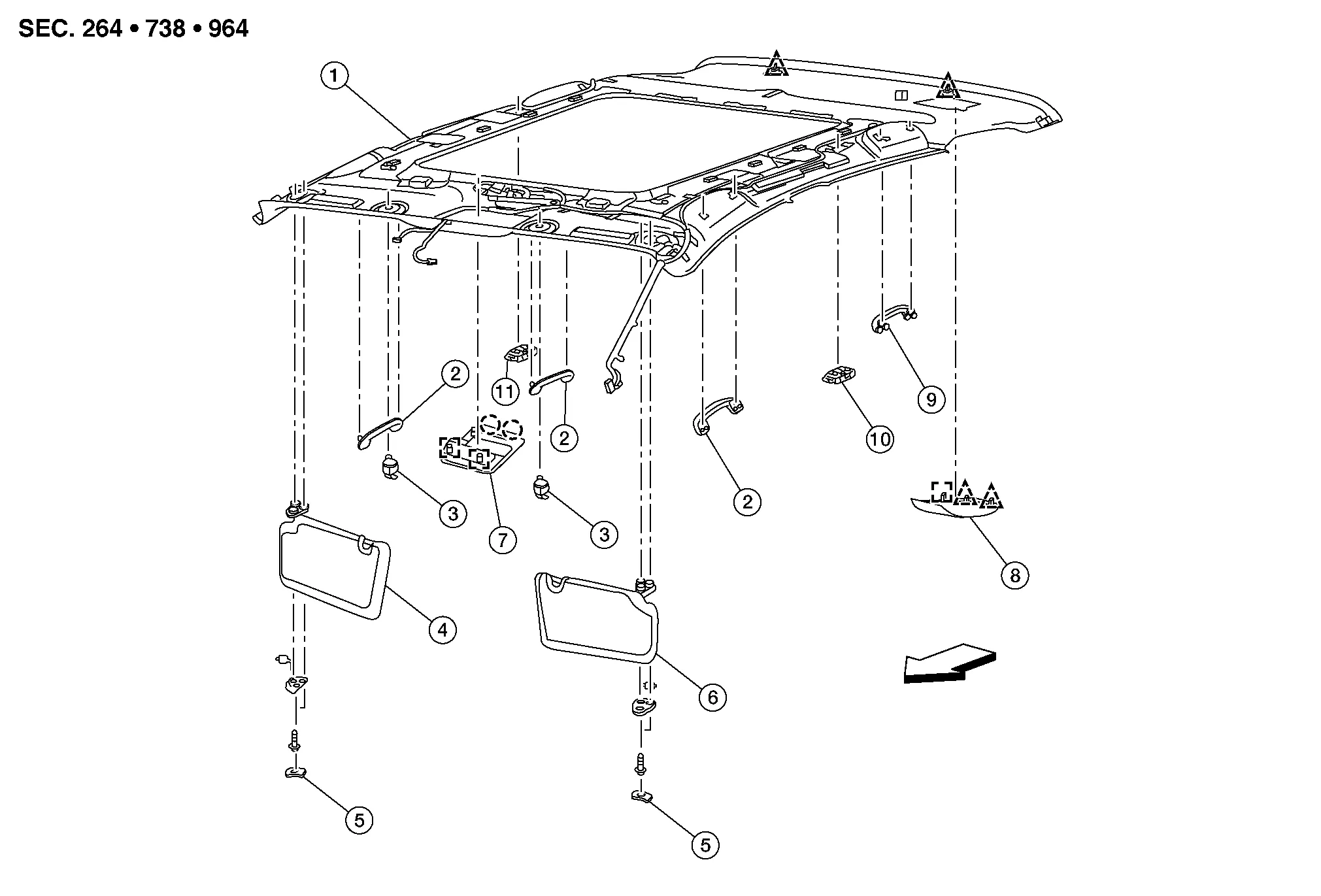
| 1. | Headlining | 2. | Assist grip (without coat hanger) | 3. | Sun visor holder (LH/RH) |
| 4. | Sun visor (RH) | 5. | Sun visor cover (LH/RH) | 6. | Sun visor (LH) |
| 7. | Front room/map lamp assembly | 8. | Rear seat belt center retractor finisher | 9. | Assist grip (with coat hanger) |
| 10. | Personal lamp 2nd row (LH) | 11. | Personal lamp 2nd row (RH) |  |
Pawl |
 |
Front |  |
Clip |  |
Metal clip |
WITHOUT PANORAMIC ROOF GLASS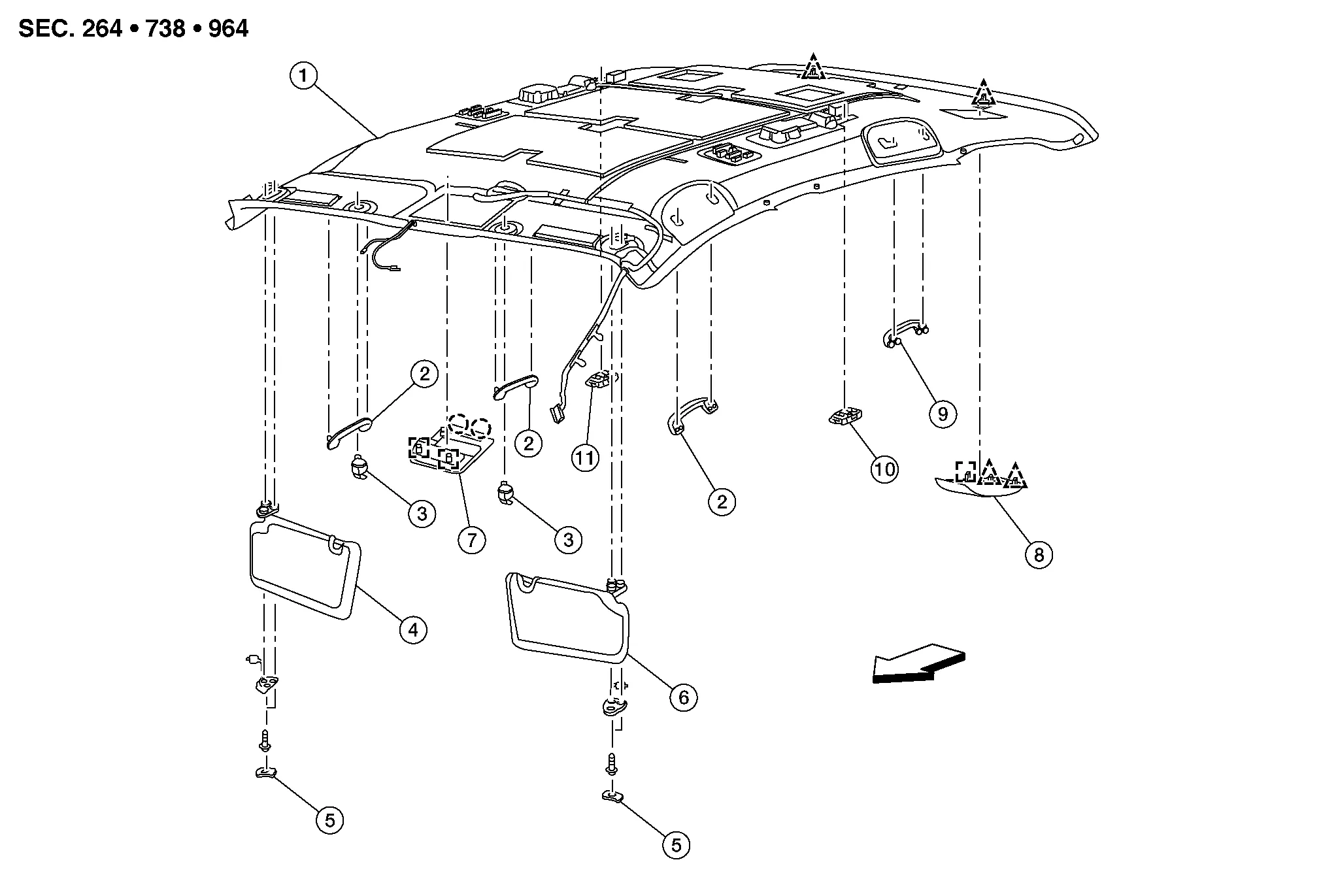
| 1. | Headlining | 2. | Assist grip (without coat hanger) | 3. | Sun visor holder (LH/RH) |
| 4. | Sun visor (RH) | 5. | Sun visor cover (LH/RH) | 6. | Sun visor (LH) |
| 7. | Front room/map lamp assembly | 8. | Rear seat belt center retractor finisher | 9. | Assist grip (with coat hanger) |
| 10. | Personal lamp 2nd row (LH) | 11. | Personal lamp 2nd row (RH) | |
Pawl |
|
Front | |
Clip | |
Metal clip |
REMOVAL
Remove sun visor cover (LH/RH) (1) by inserting a suitable tool (A) as shown.
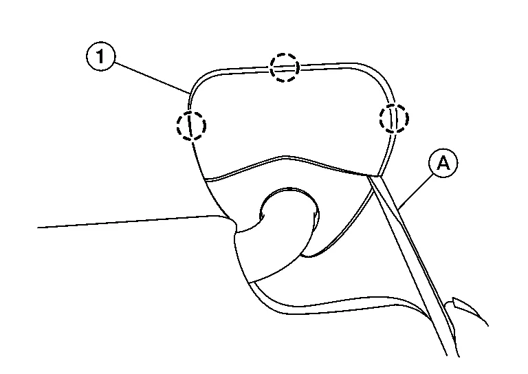
: Pawl
CAUTION:
Do not damage headlining or sun visor cover surface.
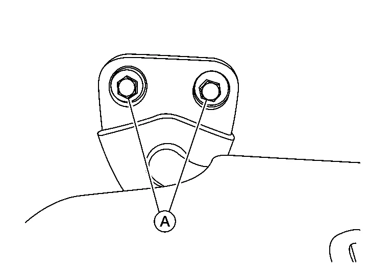
Remove sun visor bolts (A) (LH/RH) then disconnect harness connectors and remove .
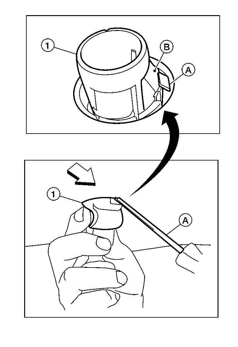
Insert a suitable tool (A) at approximately a 30 degree angle into sun visor holder notch on front of sun visor holder (1). Press in to release locking tab (B). While holding in locking tab (B), turn sun visor holder (1) 90 degrees to release it from headliner.
-
If sun visor holder (1) does not fully rotate, make sure that suitable tool (A) is pressing in on locking tab (B) and is not positioned under locking tab (B). Reinsert suitable tool (A) as necessary to release locking tab (B).
-
: Front
CAUTION:
Do not force sun visor holder when removing as locking tab may be damaged if suitable tool is not positioned correctly.
Disconnect the harness connector from the inside mirror.
Remove front assist grip (LH/RH) and rear assist grip (LH/RH).

Remove front pillar finisher (LH/RH). Refer to Removal and Installation.
Remove center pillar upper finisher (LH/RH). Refer to Removal and Installation.
Remove luggage side upper finisher (LH/RH). Refer to Removal and Installation.
Release clips using a suitable tool and remove rear seat belt center retractor finisher. Refer to Exploded View.
Disconnect harness connectors from headlining.
Using a suitable tool release headlining rear clips and remove headlining through back door.
CAUTION:
-
When removing headlining, two workers are required.
-
Do not bend headlining when removing.
-
Be careful not to scratch or damage any part of body while taking out headlining.
INSTALLATION
Installation is in the reverse order of removal.
CAUTION:
-
Do not to bend headlining when installing.
-
Install metal clips of front room/map lamp assembly and clips of rear end of headlining for positioning.
 Floor Trim
Exploded View
1.
Floor rear spacer (RH)
2.
Floor center spacer (RH)
3.
Floor front spacer (RH)
4.
Floor trim
5.
Floor front spacer (LH)
6...
 Luggage Floor Trim
Exploded View
1.
Luggage side upper finisher (RH)
2.
Luggage side upper finisher (LH)
3.
Cargo lamp
4.
Rear seat control lever finisher escutcheon (LH)
5...
Other information:
Nissan Murano (Z52) 2015-2024 Service Manual: Door Lock
Exploded View 1. Outside handle escutcheon 2. Rear gasket 3. Outside handle bracket 4. Outside handle 5. Front gasket 6. Inside door handle 7. Rear door lock Front Clip Removal and Installation REMOVALRemove the rear door outside handle...
Nissan Murano (Z52) 2015-2024 Service Manual: Diagnosis and Repair Work Flow
Work Flow NOTE: “DTC” includes DTC at the 1st trip. OBTAIN INFORMATION ABOUT SYMPTOM Refer to Diagnostic Work Sheet and interview the customer to obtain the malfunction information (conditions and environment when the malfunction occurred) as much as possible when the customer brings in the Nissan Murano vehicle...
Categories
- Manuals Home
- Nissan Murano Owners Manual
- Nissan Murano Service Manual
- Shift lock release
- Turning the AEB system on/off
- Rear bench seat adjustment
- New on site
- Most important about car
Front manual seat adjustment (if so equipped)
Your vehicle seats can be adjusted manually. For additional information about adjusting the seats, refer to the steps outlined in this section.
Forward and backward