Nissan Murano: Removal and Installation / Front Camera
REMOVAL
Remove front grille. Refer to Removal and Installation.
Disconnect the harness connector from the front camera.
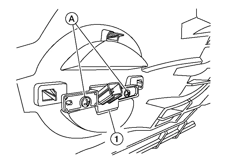
Remove screws (A) and remove front camera (1).
INSTALLATION
Installation is in the reverse order of removal.
CAUTION:
Perform the calibration and perform the writing to the around view monitor control unit when removing and replacing each camera, removing the camera mounting parts (front grille, door mirror, etc.) and replacing the around view monitor control unit. Refer to Description.
 Around View Monitor Control Unit
Exploded View
1.
Instrument panel assembly
2.
Around view monitor control unit
Removal and Installation
REMOVALNOTE:
Before replacing around view monitor control unit, perform “Before Replace ECU” of “Read / Write Configuration” to save or print current Nissan Murano vehicle specification...

Other information:
Nissan Murano (Z52) 2015-2024 Owners Manual: Replacing wheels and tires
When replacing a tire, use the same size, tread design, speed rating and load carrying capacity as originally equipped. For additional information, refer to “Wheels and tires” in the “Technical and consumer information” section of this manual...
Nissan Murano (Z52) 2015-2024 Owners Manual: Vehicle-to-vehicle distance control mode switches
The system is operated by the CRUISE ON/OFF switch and four control switches, all mounted on the steering wheel. CANCEL switch:Deactivates the system without erasing the set speed. RES/+ switch:Resumes set speed or increases speed incrementally...
Categories
- Manuals Home
- Nissan Murano Owners Manual
- Nissan Murano Service Manual
- Tire rotation
- Turning the AEB system on/off
- Fuel recommendation
- New on site
- Most important about car
Unfastening the seat belts. Checking seat belt operation
Unfastening the seat belts

To unfasten the seat belt, press the button
on the buckle  . The seat belt
automatically
retracts.
. The seat belt
automatically
retracts.
Copyright © 2026 www.nimurano.com