Nissan Murano: Unit Disassembly and Assembly / Drive Pinion
 |
Stud bolt |  |
Connector bracket |  |
Reamer bolt |
 |
Electric controlled coupling assembly |  |
Wave spring |  |
Drive pinion oil seal |
 |
Drive pinion lock nut |  |
Pinion front bearing |  |
Gear carrier |
 |
Collapsible spacer |  |
Drive pinion adjusting shim |  |
Pinion rear bearing |
 |
Drive pinion |  |
Drive gear |  |
Differential case |
 |
Side bearing |  |
Side bearing adjusting shim |  |
Side oil seal |
 |
Rear cover |  |
Stud bolt |  |
Gasket |
 |
Drain plug |  |
Filler plug |  |
Pinion mate thrust washer |
 |
Pinion mate gear |  |
Side gear thrust washer |  |
Side gear |
 |
Pinion mate shaft |  |
Lock pin | ||
 |
Oil seal lip |  |
Screw hole | ||
 : N·m (kg-m, in-lb) : N·m (kg-m, in-lb) |
|||||
 : N·m (kg-m, ft-lb) : N·m (kg-m, ft-lb) |
|||||
 : Always replace after every disassembly. : Always replace after every disassembly. |
|||||
 : Select with proper thickness. : Select with proper thickness. |
|||||
 : Apply gear oil. : Apply gear oil. |
|||||
| *: Apply anti-corrosion oil. |
|||||
 : Apply multi purpose grease. : Apply multi purpose grease. |
|||||
 : Apply Genuine Silicone RTV or equivalent. Refer to Recommended Chemical Products and Sealants. : Apply Genuine Silicone RTV or equivalent. Refer to Recommended Chemical Products and Sealants. |
|||||
 : Apply Genuine High Strength Thread Locking Sealant or equivalent. Refer to Recommended Chemical Products and Sealants. : Apply Genuine High Strength Thread Locking Sealant or equivalent. Refer to Recommended Chemical Products and Sealants. |
|||||
DISASSEMBLY
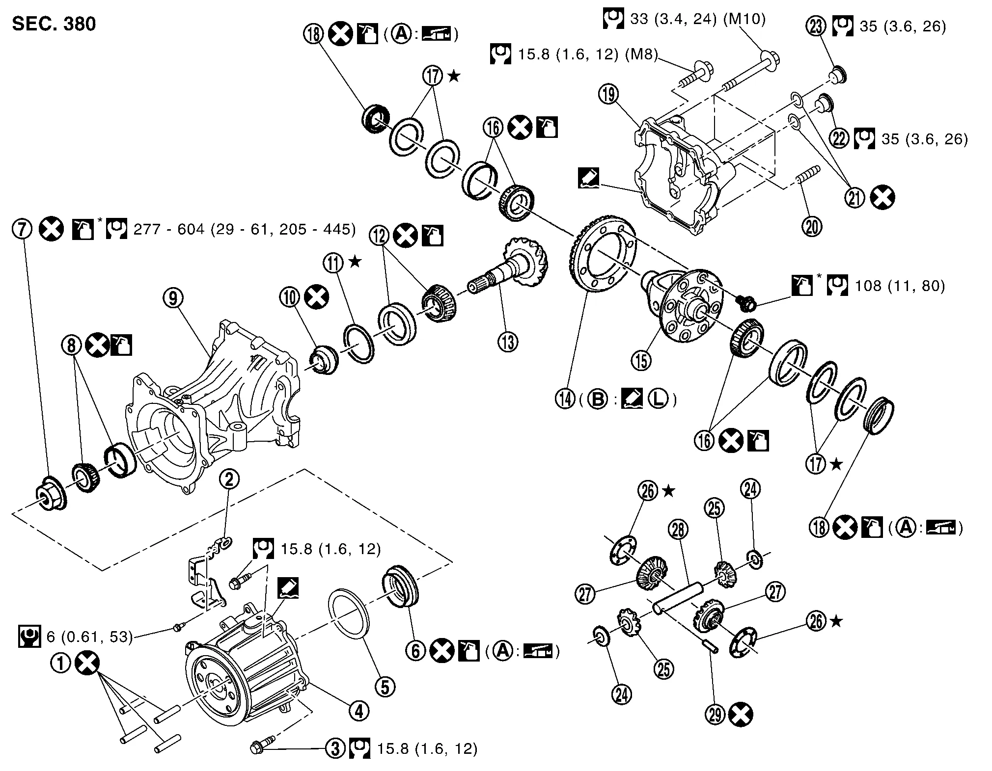
Remove electric controlled coupling assembly. Refer to Disassembly and Assembly.
Remove differential assembly. Refer to Disassembly and Assembly.
Remove drive pinion oil seal, using oil seal remover (commercial service tool).
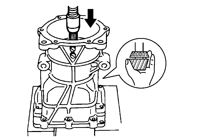
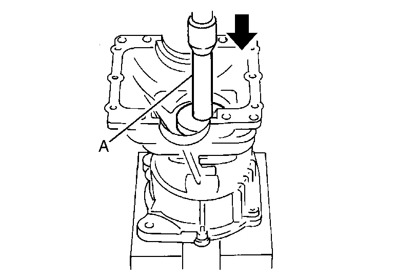
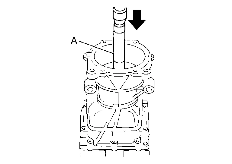
Fit drive pinion socket (A) onto drive pinion spline. Remove drive pinion lock nut, using the pinion nut wrench (B).

| A | : Drive pinion socket [SST: KV38109500 ( — )] |
| B | : Pinion nut wrench [SST: KV38109400 ( — )] |
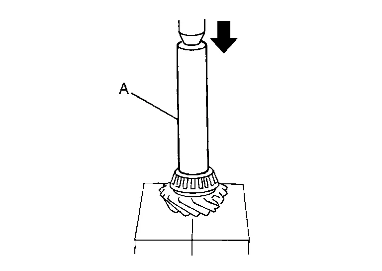
Press drive pinion assembly out of gear carrier.
CAUTION:
Do not drop drive pinion assembly.
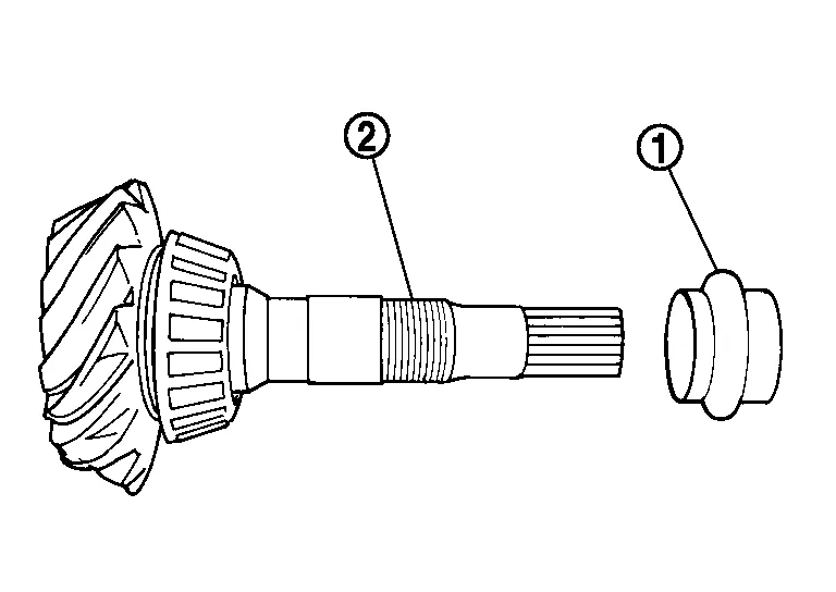
Remove pinion front bearing inner race.
Remove collapsible spacer.
Remove pinion rear bearing inner race from drive pinion, using the separator (A) and the puller (B).

| A | : Separator (commercial service tool) |
| B | : Puller (commercial service tool) |
Using a brass rod or equivalent (A), tap pinion front bearing outer race evenly from the 2 cutouts on gear carrier and remove pinion front bearing outer race.
CAUTION:
Be careful not to damage gear carrier.
Using a brass rod or equivalent (A), tap drive pinion adjusting shim evenly from the 2 cutouts on gear carrier and remove drive pinion adjusting shim and pinion rear bearing outer race.
CAUTION:
Be careful not to damage gear carrier.
Perform inspection after disassembly. Refer to Inspection.
ASSEMBLY
Install a drive pinion adjusting shim of the same thickness as was installed prior to disassembly. Press pinion rear bearing outer race into gear carrier, using the drift (A) [SST: ST33200000 (J-26082)].
CAUTION:
-
At first, using a hammer, tap bearing outer race until it becomes flush to gear carrier.
-
Do not reuse pinion rear bearing outer race.
Press pinion front bearing outer race into gear carrier, using the drift (A) [SST: ST33230000 (J-25805-01)].
CAUTION:
-
At first, using a hammer, tap bearing outer race until it becomes flush to gear carrier.
-
Do not reuse pinion front bearing outer race.
Press pinion rear bearing inner race to drive pinion, using the drift (A) [SST: ST23860000 ( — )].
CAUTION:
Do not reuse pinion rear bearing inner race.
Check and adjust the tooth contact and back lash of drive gear and drive pinion following the procedure below.Assemble drive pinion into gear carrier.
CAUTION:
-
Do not assemble collapsible spacer.
-
Apply gear oil to pinion rear bearing.
CAUTION:
-
Do not reuse pinion front bearing inner race.
-
Apply gear oil to pinion front bearing.
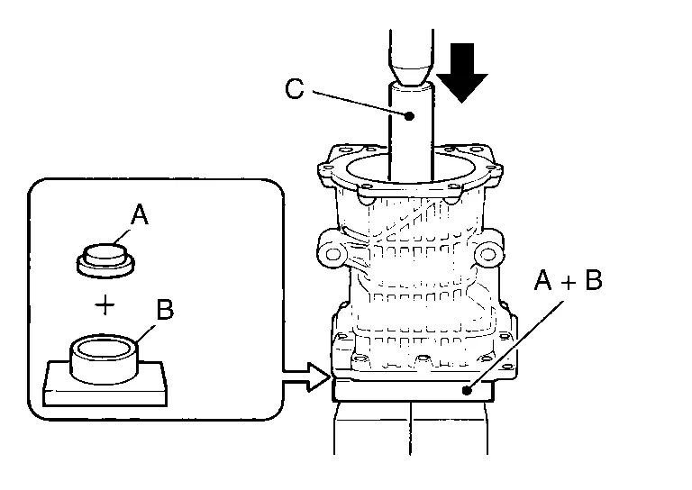
| A | : Drift [SST: KV40100610 (J-26089)] |
| B | : Press stand [SST: ST38220000 ( — )] |
| C | : Drift [SST: ST23860000 ( — )] |
 NOTE:
NOTE:
Use removed drive pinion lock nut only for the preload measurement.
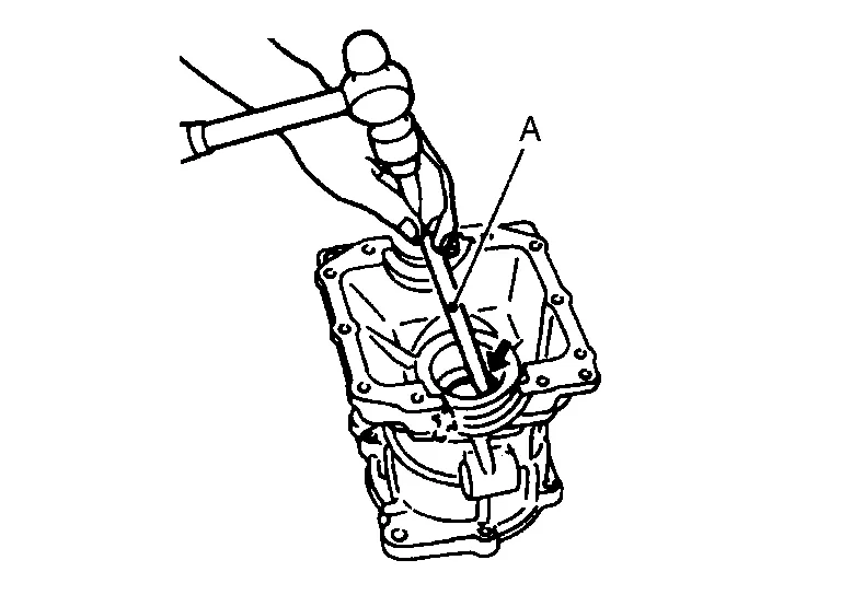
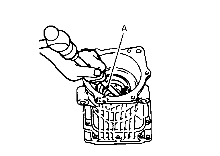
Rotate drive pinion more than 20 times to adjust bearing. Fit the drive pinion socket (A) onto the drive pinion. Using the pinion nut wrench (B), tighten drive pinion lock nut holding drive pinion, while adjusting pinion bearing preload torque using preload gauge (C).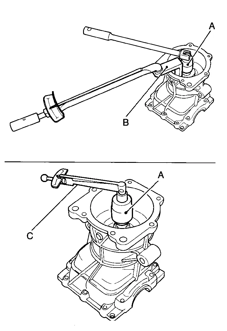
| A | : Drive pinion socket [SST: KV38109500 ( — )] |
| B | : Pinion nut wrench [SST: KV38109400 ( — )] |
| C | : Preload gauge [SST: ST3127S000 (J-25765-A)] |
| Pinion bearing preload | : Refer to Preload Torque. |
CAUTION:
Drive pinion lock nut is tightened with no collapsible spacer. Be careful not to overtighten it. While measuring the preload, tighten it by 5° to 10°.
Install new side bearing adjusting shims (2 pieces for one side) with the same thickness or re-install the old ones to the same mounting position they were in prior to disassembly. Install differential assembly to gear carrier. Refer to Disassembly and Assembly.CAUTION:
Apply differential gear oil to the side bearings.
Check and adjust tooth contact, drive gear to drive pinion backlash. Refer to Adjustment. Remove differential assembly. Remove drive pinion assembly from gear carrier Remove drive pinion nut and press drive pinion assembly out of gear carrier. Remove pinion front bearing inner race.Assemble collapsible spacer to drive pinion .
CAUTION:
-
Be careful of the mounting direction of collapsible spacer.
-
Do not reuse collapsible spacer.
Assemble drive pinion into gear carrier.
CAUTION:
Apply gear oil to pinion rear bearing.
Assemble pinion front bearing inner race to drive pinion assembly.
CAUTION:
-
Do not reuse pinion front bearing inner race.
-
Apply gear oil to pinion front bearing.
Using the drifts (A and C) and press stand (B), press pinion front bearing inner race to drive pinion as far as drive pinion lock nut can be tightened.
| A | : Drift [SST: KV40100610 (J-26089)] |
| B | : Press stand [SST: ST38220000 ( — )] |
| C | : Drift [SST: ST23860000 ( — )] |
Apply anti-corrosion oil to the thread and seat of drive pinion lock nut, and temporarily tighten drive pinion lock nut to drive pinion.
CAUTION:
Do not reuse drive pinion lock nut.
Fit the drive pinion socket (A) onto the drive pinion. While holding drive pinion, tighten drive pinion lock nut within the limits of specified torque so as to keep the pinion bearing preload within a standard values, using the pinion nut wrench (B) and the preload gauge (C).
| A | : Drive pinion socket [SST: KV38109500 ( — )] |
| B | : Pinion nut wrench [SST: KV38109400 ( — )] |
| C | : Preload gauge [SST: ST3127S000 (J-25765-A)] |
| Drive pinion lock nut tightening torque | : Refer to Exploded View. |
| Pinion bearing preload | : Refer to Preload Torque. |
CAUTION:
-
Adjust the lower limit of the drive pinion lock nut tightening torque first.
-
If the preload torque exceeds the specified value, replace collapsible spacer and tighten it again to adjust. Do not loose n drive pinion lock nut to adjust the preload torque.
-
After adjustment, rotate drive pinion back and forth 2 to 3 times to check for unusual noise, rotation malfunction, and other malfunctions.
Install differential assembly. Refer to Disassembly and Assembly.
CAUTION:
Do not install rear cover at this timing.
Check and adjust drive gear runout, tooth contact, and drive gear to drive pinion backlash. Refer to Adjustment.
Remove dummy cover set, then install rear cover, and side oil seal. Refer to Disassembly and Assembly.
Check total preload torque. Refer to Adjustment.
Using the drift (A) [SST: ST35271000 (J-26091)], install drive pinion oil seal within the dimension (D) shown as follows.
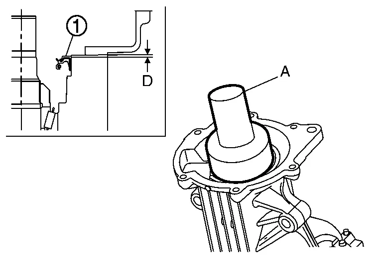
| D | : 0.8 – 1.2 mm (0.031 – 0.047 in) |
CAUTION:
-
Do not reuse oil seal.
-
When installing, do not incline oil seal.
-
Apply multi-purpose grease onto oil seal lips, and gear oil onto the circumference of oil seal.
Install electric controlled coupling assembly. Refer to Disassembly and Assembly.
INSPECTION AFTER DISASSEMBLY
Drive Gear and Drive Pinion
Clean up the disassembled parts.
If the gear teeth never mesh or line-up correctly, determine the cause and adjust or replace as necessary.
If the gears are worn, cracked, damaged, pitted or chipped (by friction) noticeably, replace with new drive gear and drive pinion as a set.
Bearing
Clean up the disassembled parts.
If any chipped (by friction), pitted, worn, rusted or scratched marks, or unusual noise from the bearing is observed, replace as a bearing assembly (as a new set).
Oil Seal
Whenever disassembled, replace.
If wear, deterioration of adherence (sealing force lips), or damage is detected on the lips, replace them.
 Differential Assembly
Exploded View
Stud bolt
Connector bracket
Reamer bolt
Electric controlled coupling assembly
Wave spring
Drive pinion oil seal
Drive pinion lock nut
Pinion front bearing
Gear carrier
Collapsible spacer
Drive pinion adjusting shim
Pinion rear bearing
Drive pinion
Drive gear
Differential case
Side bearing
Side bearing adjusting shim
Side oil seal
Rear cover
Stud bolt
Gasket
Drain plug
Filler plug
Pinion mate thrust washer
Pinion mate gear
Side gear thrust washer
Side gear
Pinion mate shaft
Lock pin
Oil seal lip
Screw hole
: N·m (kg-m, in-lb)
: N·m (kg-m, ft-lb)
: Always replace after every disassembly...
 Service Data and Specifications (sds). Service Data and Specifications (sds)
General Specifications
Applied model Axle AWD
Engine VQ35DE
Transaxle CVT
Final drive model R145
Gear ratio
2.466
Number of teeth (Drive gear/Drive pinion)
37/15
Number of pinion gears
2
Drive pinion adjustment spacer type
Collapsible
Oil capacity
Refer to Fluids and Lubricants...
Other information:
Nissan Murano (Z52) 2015-2024 Service Manual: Brake System :: Service Data and Specifications (sds). Service Data and Specifications (sds)
General Specifications Unit: mm (in) Master cylinder Cylinder bore diameter 27 (1.063) Control valve Valve type Electric brake force distribution Recommended brake fluid Refer to Fluids and Lubricants. Brake Pedal Unit: mm (in) Item Standard Brake pedal height (H) 196...
Nissan Murano (Z52) 2015-2024 Service Manual: Door Striker
Removal and Installation REMOVALRemove bolts and front door striker.INSTALLATIONInstallation is in the reverse order of removal.CAUTION: Do not reuse front door striker bolts. After installation, check front door open/close operation. If necessary, adjust front door striker...
Categories
- Manuals Home
- Nissan Murano Owners Manual
- Nissan Murano Service Manual
- Fuel recommendation
- Checking engine oil level
- Intelligent Forward Collision Warning (I-FCW)
- New on site
- Most important about car
Front manual seat adjustment (if so equipped)
Your vehicle seats can be adjusted manually. For additional information about adjusting the seats, refer to the steps outlined in this section.
Forward and backward
