Nissan Murano: Driveline :: Rear Final Drive: R145 / Service Data and Specifications (sds). Service Data and Specifications (sds)
Nissan Murano (Z52) 2015-2024 Service Manual / Transmission & Driveline / Driveline :: Rear Final Drive: R145 / Service Data and Specifications (sds). Service Data and Specifications (sds)
| Applied model | Axle | AWD | |
|---|---|---|---|
| Engine | VQ35DE | ||
| Transaxle | CVT | ||
| Final drive model | R145 | ||
| Gear ratio | 2.466 | ||
| Number of teeth (Drive gear/Drive pinion) | 37/15 | ||
| Number of pinion gears | 2 | ||
| Drive pinion adjustment spacer type | Collapsible | ||
| Oil capacity | Refer to Fluids and Lubricants. | ||
Unit: N·m (kg-m, in-lb)
| Item | Standard |
|---|---|
| Pinion bearing (P1) | 0.69 – 1.18 (0.07 – 0.12, 7 – 10) |
| Side bearing (P2) | 0.66 – 1.00 (0.07 – 0.10, 6 – 8) |
|
Side bearing to pinion bearing (Total preload) (Total preload = P1 + P2) |
1.35 – 2.18 (0.14 – 0.22, 12 – 19) |
Unit: mm (in)
| Item | Standard | ||
|---|---|---|---|
| Drive gear back face runout | 0.05 (0.0020) or less |
Unit: mm (in)
| Item | Standard |
|---|---|
| Drive gear to drive pinion gear | 0.10 – 0.15 (0.0039 – 0.0059) |
Unit: mm (in)
| Item | Standard | ||
|---|---|---|---|
| Side gear backlash (Clearance between side gear and differential case) |
0.10 (0.004) or less (Each gear should rotate smoothly without excessive resistance during differential motion.) |
 Drive Pinion
Exploded View
Stud bolt
Connector bracket
Reamer bolt
Electric controlled coupling assembly
Wave spring
Drive pinion oil seal
Drive pinion lock nut
Pinion front bearing
Gear carrier
Collapsible spacer
Drive pinion adjusting shim
Pinion rear bearing
Drive pinion
Drive gear
Differential case
Side bearing
Side bearing adjusting shim
Side oil seal
Rear cover
Stud bolt
Gasket
Drain plug
Filler plug
Pinion mate thrust washer
Pinion mate gear
Side gear thrust washer
Side gear
Pinion mate shaft
Lock pin
Oil seal lip
Screw hole
: N·m (kg-m, in-lb)
: N·m (kg-m, ft-lb)
: Always replace after every disassembly...
 Front Axle :: Precaution. Precautions
Precaution for Supplemental Restraint System (SRS) "AIR BAG" and "SEAT BELT PRE-TENSIONER"
The Supplemental Restraint System such as “AIR BAG” and “SEAT BELT PRE-TENSIONER”, used along with a front seat belt, helps to reduce the risk or severity of injury to the driver and front passenger for certain types of collisions...
Other information:
Nissan Murano (Z52) 2015-2024 Service Manual: Throttle Control
System Description SYSTEM DIAGRAM*: ECM determines the start signal status by the signals of engine speed and battery voltage.SYSTEM DESCRIPTIONECM calculates the value of signal transmitted from the accelerator pedal and activates the throttle valve by transmitting a control signal to the electric throttle control actuator...
Nissan Murano (Z52) 2015-2024 Service Manual: B2195 Anti-Scanning
DTC Description DTC DETECTION LOGIC DTC No. CONSULT screen terms (Trouble diagnosis content) DTC Detection Condition B2195 ANTI-SCANNING (Anti-scanning) Diagnosis condition When ignition switch ON. Signal (terminal) — Threshold ID verification between BCM and ECM that is out of the designated specification is detected Diagnosis delay time — POSSIBLE CAUSEID verification request out of the designated specificationFAIL-SAFEInhibit engine cranking DTC Confirmation Procedure PERFORM DTC CONFIRMATION PROCEDURE CONSULT Ignition switch ON...
Categories
- Manuals Home
- Nissan Murano Owners Manual
- Nissan Murano Service Manual
- All-Wheel Drive (AWD) (if so equipped)
- Turning the AEB system on/off
- Fuel recommendation
- New on site
- Most important about car
Driver and passenger supplemental knee air bag
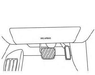
Driver’s side
The knee air bag is located in the knee bolster, on the driver’s and passenger’s side. All of the information, cautions and warnings in this manual apply and must be followed. The knee air bag is designed to inflate in higher severity frontal collisions, although it may inflate if the forces in another type of collision are similar to those of a higher severity frontal impact. It may not inflate in certain collisions.
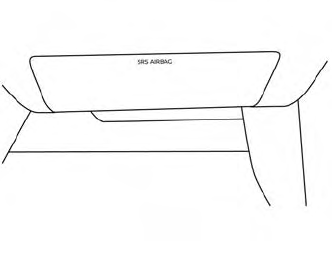
Passenger’s side

Copyright © 2026 www.nimurano.com