
Nissan Murano: Service Information / Body Welding and Precautions
Nissan Murano (Z52) 2015-2024 Service Manual / Body Exterior, Doors, Roof & Vehicle Security / Body Repair :: Fundamentals / Service Information / Body Welding and Precautions
 Paintless Dent Repair
Paintless Dent Repair
Paintless dent repair is one type of panel repair technique. This technique is used to repair irregularities on painted outer panels without damaging the painted surface...
 Outline of Welding
Features of Welding
No restrictions on the shape of joint
Reduction in weight compared to using of bolts or rivets
Great strength
Airtight and watertight
High working efficiency
Some welding processes require higher welding skills...
Other information:
Nissan Murano (Z52) 2015-2024 Owners Manual: Door locks/unlocks precaution
Do not push the door handle request switch with the Intelligent Key held in your hand as illustrated. The close distance to the door handle will cause the Intelligent Key system to have difficulty recognizing that the Intelligent Key is outside the vehicle...
Nissan Murano (Z52) 2015-2024 Service Manual: U1010 Control Unit(can)
DTC Description Initial diagnosis of A/C auto amp.DTC DETECTION LOGIC DTC No. CONSULT screen terms (Trouble diagnosis content) DTC detection condition U1010 CONTROL UNIT(CAN) [Control unit (CAN)] Diagnosis condition When ignition switch is ON...
Categories
- Manuals Home
- Nissan Murano Owners Manual
- Nissan Murano Service Manual
- System malfunction
- Memory storage function (key-link)
- Checking engine oil level
- New on site
- Most important about car
Fuel gauge
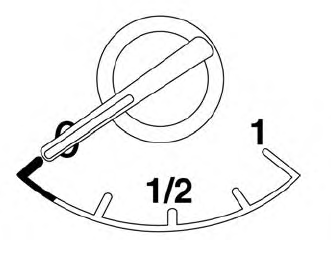
The gauge indicates the approximate fuel level in the tank.
The gauge may move slightly during braking, turning, acceleration, or going up or down hills.
The gauge needle returns to 0 (Empty) after the ignition switch is placed in the OFF position.

Copyright © 2026 www.nimurano.com