Nissan Murano: Body Welding and Precautions / Electric Resistance Spot Welding
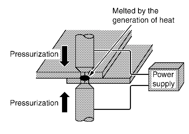
Resistance spot welding is a kind of electric resistance welding. It is classified as pressure welding. Two or three sheets of metal are overlapped and pressed, and current is passed through the mating surfaces. As the current flows, the metals melt due to Joule heat at the mating surfaces and are joined by the pressure.
-
Short welding time and high efficiency compared to other welding processes
-
Minimum thermal strain due to partial heating
-
No need to finish the welded surface
-
Less rust formation compared to other welding processes due to application of conductive sealer
-
Great welding skill is not needed. Uniform weld strength can be obtained regardless of worker's skill
-
Heavy welding machine is required to produce high current
-
Most suitable for welding thin sheet metals
-
The condition of the weld is difficult to check from the outside
-
Paint must be removed from the surfaces to be welded
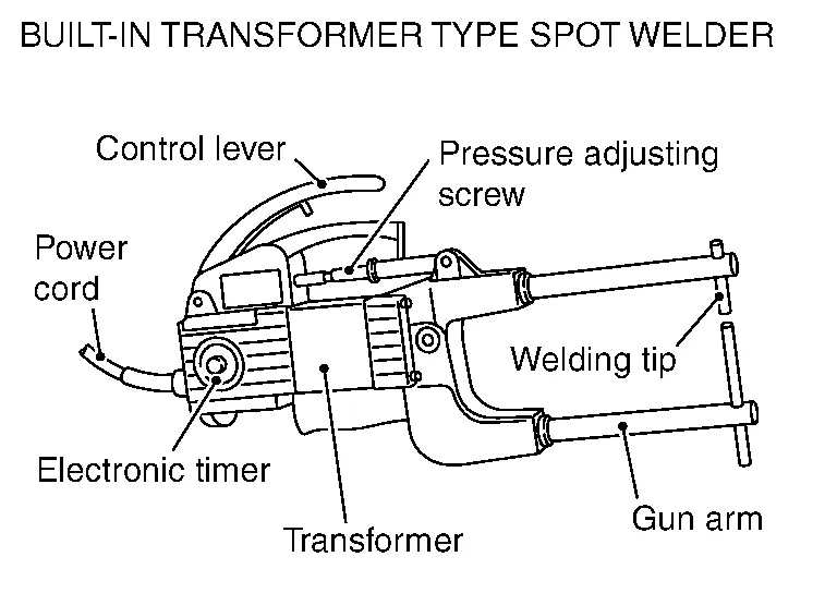
The spot welding machine consists of a transformer unit which supplies the voltage and current required for welding, a timer unit which controls the current passing time, and a welding gun.
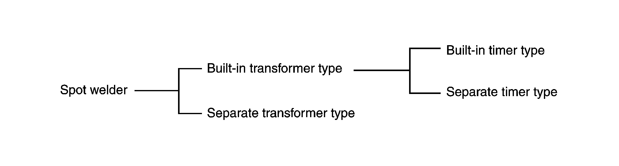
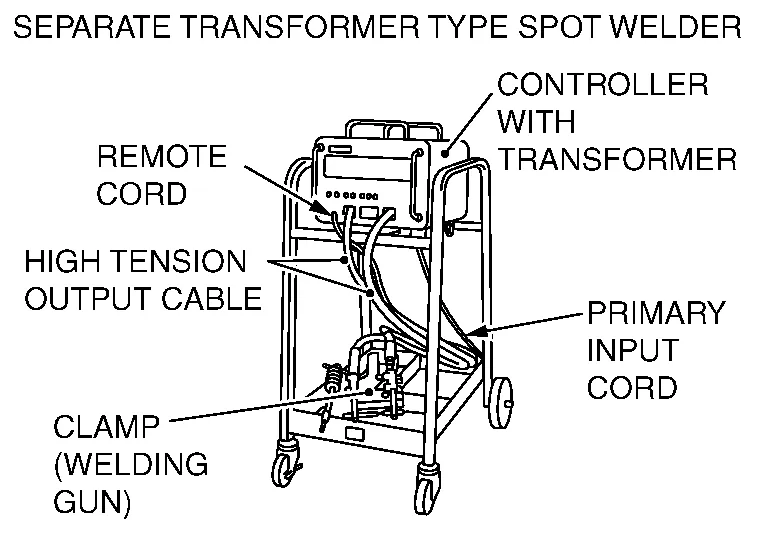
The separate transformer type includes a multi-functional type for welding of pins and washers.
|
|
|
-
Air cooling: Forced air cooling with fan
-
Water cooling: Cooling by circulating the water
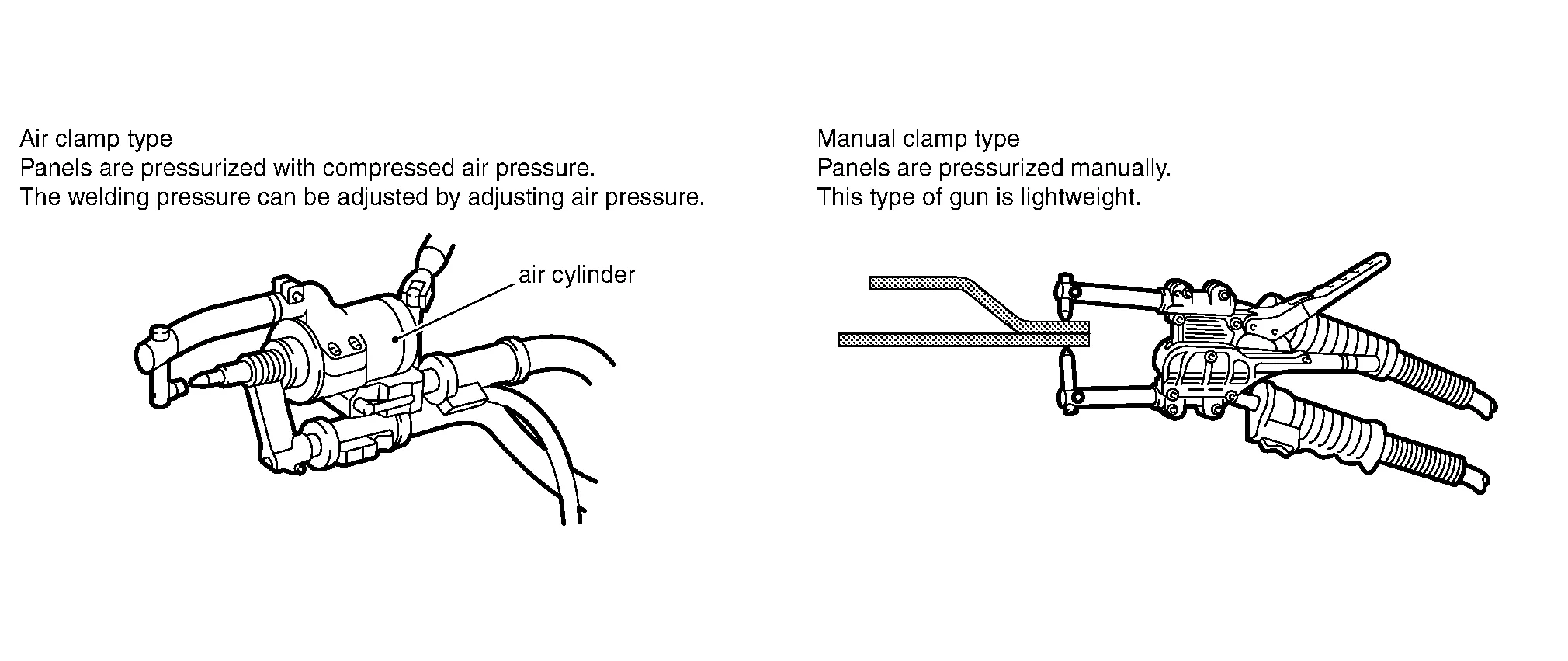
(1) TYPES OF CLAMP
 NOTE:
NOTE:
Manual Clamp Type welders don’t apply enough pressure.
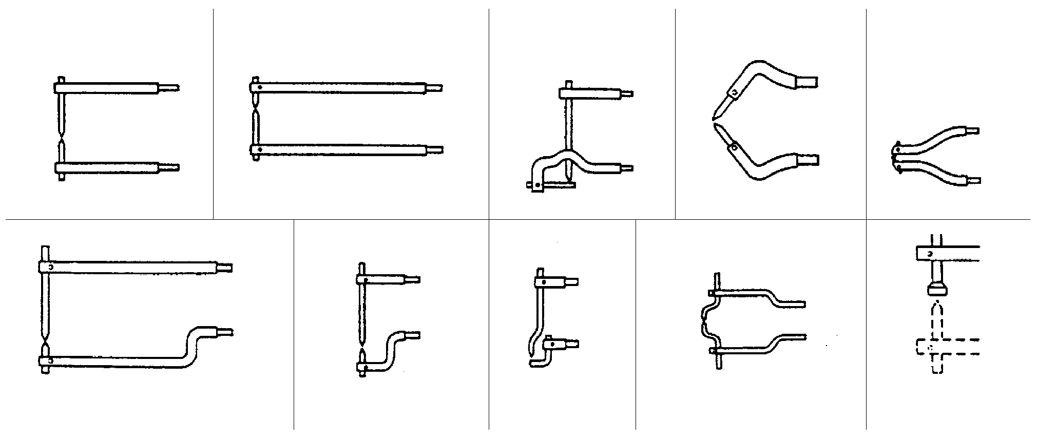
(2) ATTACHMENT ARM
-
In spot welding, 2 or 3 panels to be welded must be clamped directly at electrodes. Therefore, the disadvantage of spot welding is that there are some points at which welding cannot be performed.
-
In order to make up for this weakness, various types of attachment arms have been created.
(3) HANGING UNIT
-
The weight of guns, arms and cables has been reduced to minimize the burden on workers.
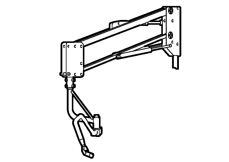
-
Depending on the unit type, the cable can simply be hung, or the gun can be hung with a cylinder.
In addition to the ordinary spot welding function, sheet metal can be pulled with the sliding hammer.
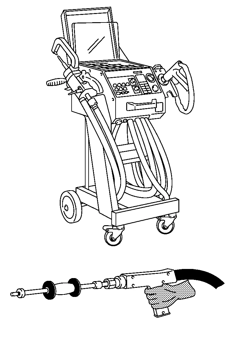
Major functions:
-
Both sided spot welding
-
One sided spot welding (Pre tack welding)
-
Spot hammer welding
-
Nuts and bolts welding
-
Carbon shrinking
-
Contact shrinking
-
Washer and pin or stud welding
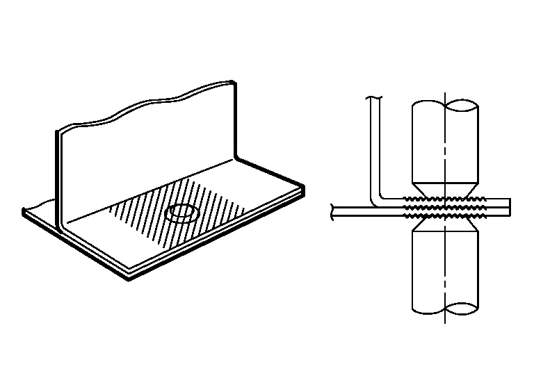
It takes 3 processes, “pressurization”, “energization”, and “retention”, to complete the spot welding.
(1) PRESSURIZATION
-
The welding points of overlapped panels are pressurized with the tip (electrode) for close contact.
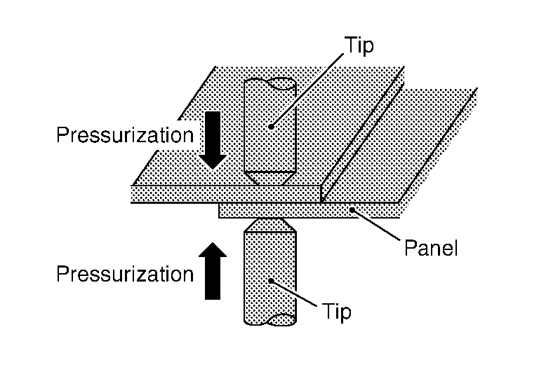
-
With the panels contacting closely, the current can run intensively.
(2) ENERGIZATION
-
With the panels being pressurized, heavy current is applied.
-
Joule heat is generated at panel mating areas, and the temperature rises sharply.
-
The panel mating areas are melted and fused together by welding pressure.
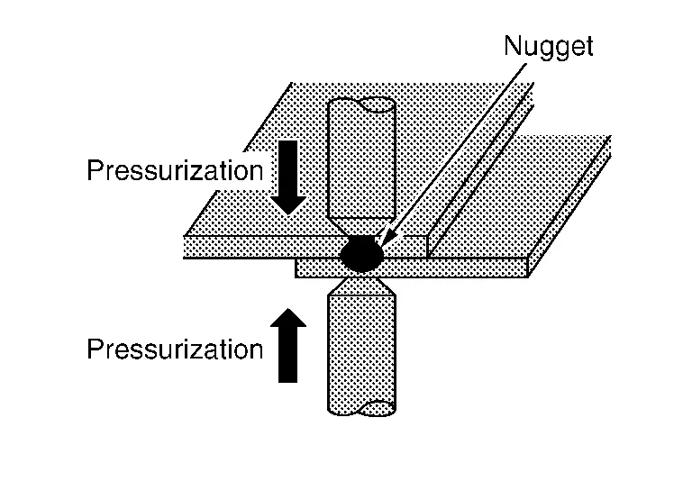
(3) RETENTION
-
Even after the current is turned off, pressure is still applied until the welded point cools down.
-
The nugget system becomes delicate by pressurization, resulting in better mechanical properties.
-
Therefore, the retention process must not be omitted.
Before beginning, thoroughly check the panel and make any necessary corrections.
(1) CLEARANCE BETWEEN WELDING SURFACES
Gaps between the surfaces to be welded cause poor current flow. Even if welding could be done without removing such gaps, the welded area would be smaller, resulting in poor strength.
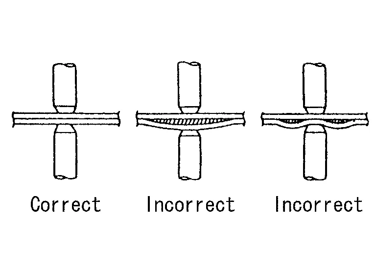
Flatten the two surfaces to remove the gaps, and clamp them tightly before welding.
Assessment of spot-weld areas
Before body components are actually joined, it must be ensured that every welding surface to be joined meets the strength requirements and is adequate for the accident safety resulting from these. To this end, test welds can be made on offcuts of the replacement part that are not required. The results of the welding can also be used for fine adjustment of the spot-welding apparatus, if necessary.
| Weld | Feature | Explanation |
|
|
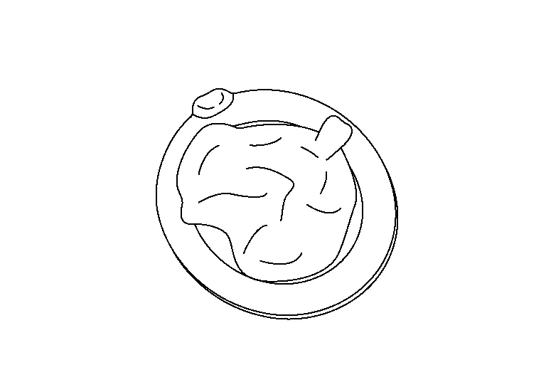
Welding spot OK | |
|
|
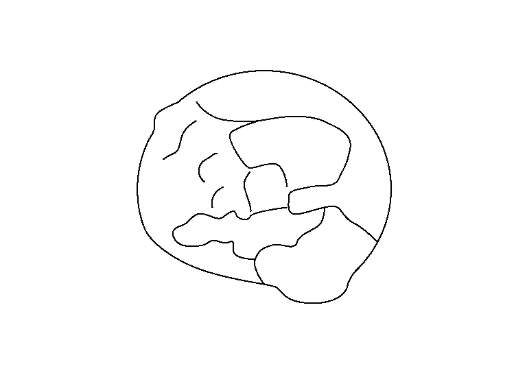
Weld penetration too deep, heat affected zone too great | Excessive build-up of heat due to raised welding current or excessive welding time. |
|
|
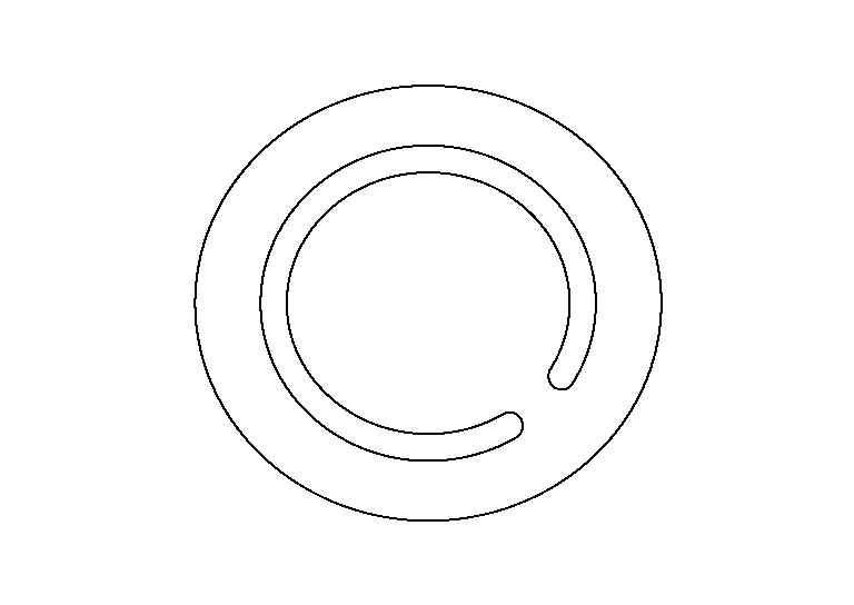
Misshapen contact point | Contaminated electrode tip. The distorted resistance measurement caused by this leads to incorrect welding parameters and, as a result, to reduced connection strength. |
|
|
Surface damage | Excessive contact resistance due to insufficient contact pressure electrodes. |
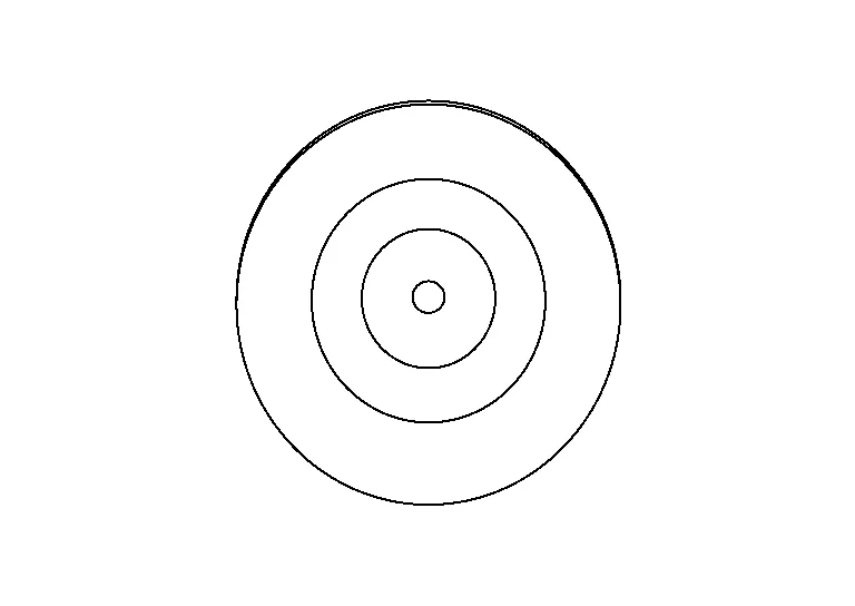
In addition to the visual assessment of the welding spots, a peel test must also be performed. To do this, the metal sheets that were previously joined with a welding spot are separated by peeling. During this test the welding spot must be pulled out of one of the two metal sheets completely. The size of the welding spot must have a certain minimum diameter.
Ø nugget > 4 x √ sheet thickness (thinnest sheet of connection). An approximate value for the diameter of the peel test can be found in the following table.
| Sheet thickness in mm | 0.8 | 1.0 | 1.2 | 1.6 |
| Diameter of weld nugget in mm | 3.6 | 4.0 | 4.4 | 5.0 |
(2) PANEL SURFACES TO BE WELDED
Paint, rust, dust, or any other contamination on the panel surfaces to be welded cause insufficient current flow and poor results.
Remove such foreign matter from the surfaces to be welded by sanding or wiping clean.
(3) CORROSION PREVENTS PROPER WELDING OF PANEL SURFACES.
Coat the surfaces to be welded with an anticorrosion agent that has high conductivity.
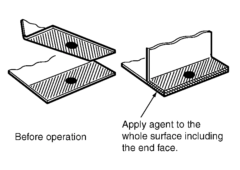
It is important to evenly apply the agent to the panel including the end face.
Perform the spot welding before the anticorrosion agent gets dry, as the agent has generally low conductivity.
Because the wet agent can move from the welding portion due to the welding pressure, that leads to the good quality of spot welding by high conductivity.
(1) SELECTION OF SPOT WELDING MACHINE
Use the direct welding method whenever possible.
(When direct welding cannot be applied, use MAG plug welding.)
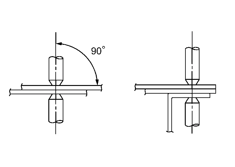
(2) APPLICATION OF ELECTRODE TIPS
Apply electrodes at right angles to the panel. If they are not applied properly, the current density will be low, resulting in poor welding strength.
(3) NUMBER OF SPOT WELDING POINTS
Generally, the capacity of repair shop spot welding machines is smaller than that of factory welding machines. Accordingly, the number of points of spot welding should be increased by 20% - 30% over the spot weld number indicated in the Body Repair Manual.
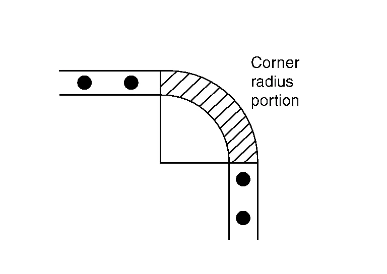
(4) WELDING CORNERS
Do not weld the curved corner. Welding this portion results in stress concentration, which leads to cracks.
Examples:
-
Upper corner of front and center pillars
-
Front upper portion of rear fender
-
Corner portion of front and rear windows
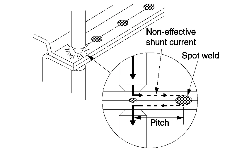
(5) MINIMUM WELDING PITCH
The minimum welding pitch varies with the thickness of panels to be welded. In general, observe the values in the following table.
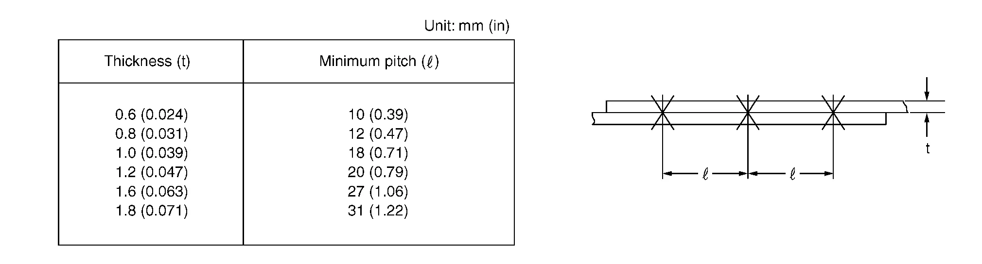
NOTE:
The excessively small pitch allows the current to flow through surrounding portions, resulting in poor welding strength.
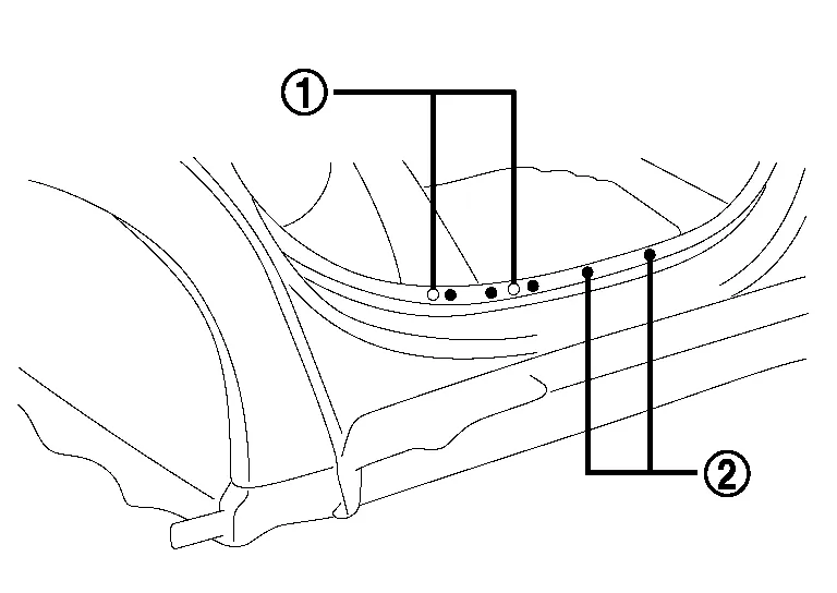
Avoid welding over previously welded areas.
As spot welded portion will become harder and thinner, the different portion should be welded as possible.
 |
Old Spot Locations |
 |
New Spot Locations |
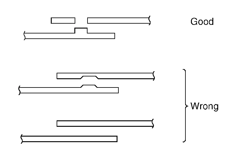
(6) MINIMUM LAP OF PANELS
Observe the following values for the lap distance of panels. Too short of a lap distance results in reduced strength and also in a strained panel.
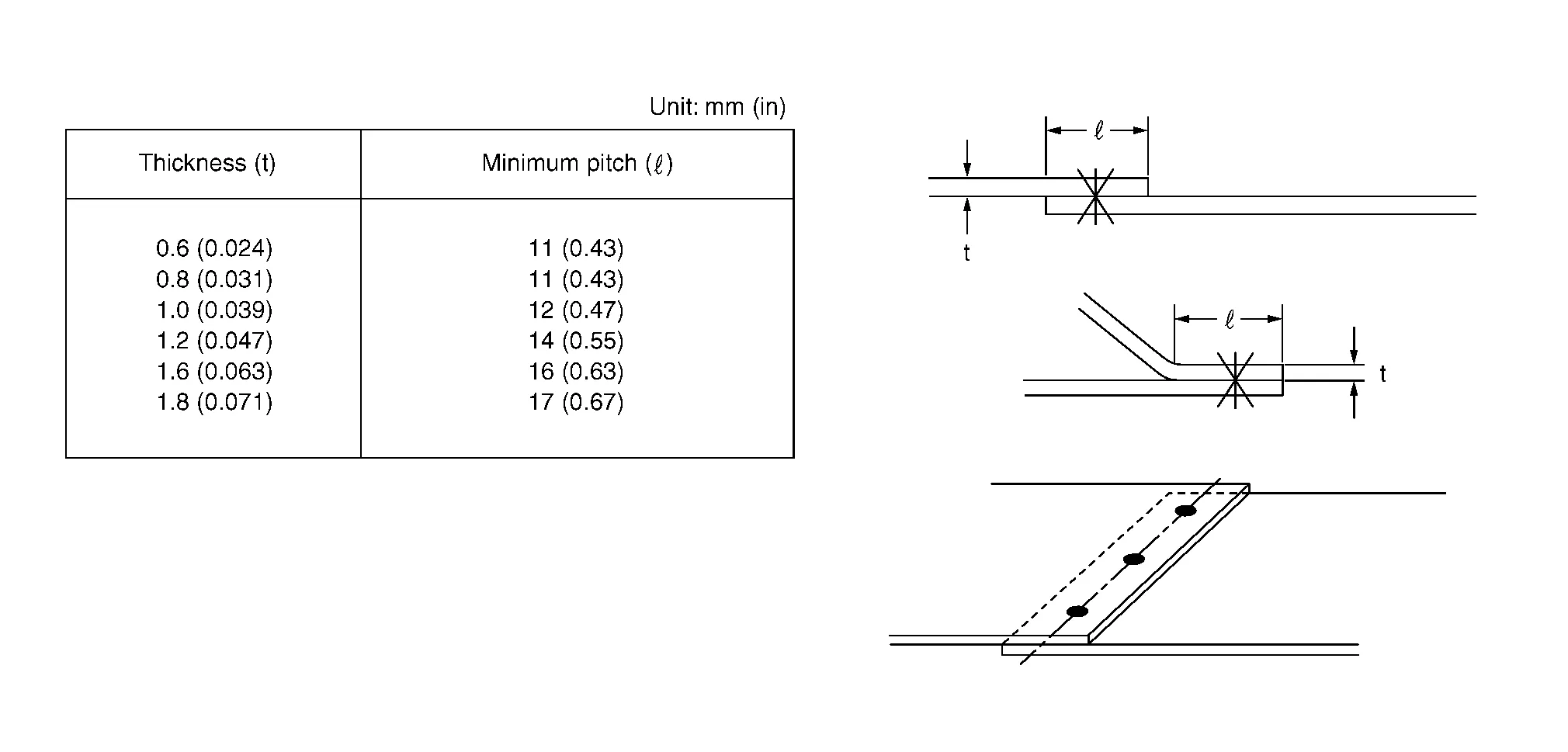
NOTE:
Be sure to spot weld at the center of the overlapped portion.
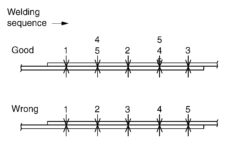
(7) SPOTTING SEQUENCE
Do not spot weld continuously in one direction only. This causes weak welding due to the shunt effect of the current. If the welding tips become red-hot, stop welding and cool the tips.
Spot welded portions can be checked by the destructive inspections explained below. They can be easily adopted when welding. Before and after welding, you should perform these destructive inspections to check the strength of the welded portions.
The welding spots should be equally spaced and arranged at the center of the flange to be welded.
(1) CHECK BY USING TEST PIECE (Confirmation before operation)
NOTE:
Clamp both test pieces together so that they will not slip or move during welding.
(a) Weld together test pieces with the same thickness as the panel to be welded.
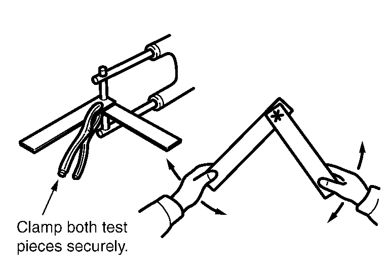
Break the weld by twisting, and examine the break.
(b) With this test, a hole should be made on one test piece by tearing at the welded portion. If no hole is formed, it indicates that the welding conditions are incorrect. Adjust the pressure, welding current, current passing time and other conditions, and repeat test until the best result is obtained.
(2) CHECK BY USING CHISEL AND HAMMER (Confirmation after welding)
(a) Insert a chisel tip between the welded panels, and tap the end until a clearance 3 mm - 4 mm (0.12 in - 0.16 in) [when the panel thickness is 0.8 mm - 1.0 mm (0.031 in - 0.039 in)] is formed between the panels. If the welded portions do not separate, it indicates that the welding has been done properly.
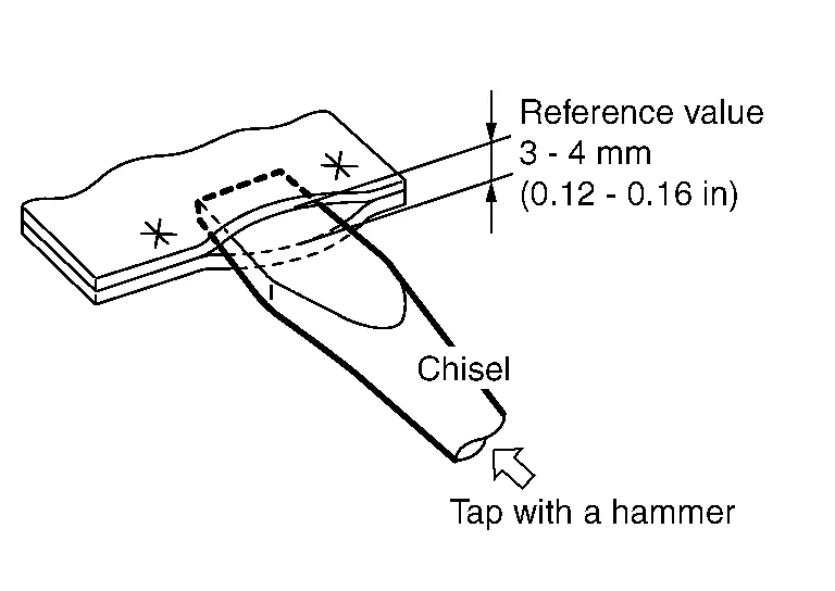
This clearance varies with the location of the welded spots, length of the flange, panel thickness, welding pitch, and other factors. Note that the value shown above is only for reference.
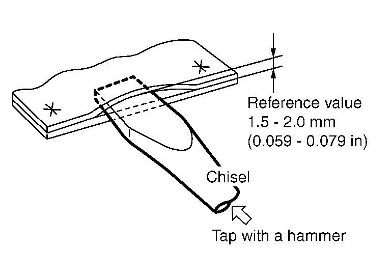
(b) If the thickness of the panels is different, the clearance must be limited to 1.5 mm - 2.0 mm (0.059 in - 0.079 in). Further opening of the panels can become a destructive test.
(c) Be sure to repair the deformed portion of the panel after inspection.
 Outline of Welding
Features of Welding
No restrictions on the shape of joint
Reduction in weight compared to using of bolts or rivets
Great strength
Airtight and watertight
High working efficiency
Some welding processes require higher welding skills...
 Mag Welding
MAG Welding
MAG welding uses the heat of an electric arc to join two pieces of metal by fusing both the metal and the electrode. For auto repair MAG (Metal Active Gas) are the types of arc welding most often used...
Other information:
Nissan Murano (Z52) 2015-2024 Service Manual: C1b50-49 Side Radar Malfunction
DTC Description DTC DETECTION LOGIC DTC No. CONSULT screen terms (Trouble diagnosis content) DTC detection condition C1B50-49 SIDE RDR MALFUNCTION (Side radar malfunction) Diagnosis condition When ignition switch is ON. Signal (terminal) – Threshold Side radar malfunction Diagnosis delay time – POSSIBLE CAUSESide radar LHFAIL-SAFEThe following systems are canceled: Blind Spot Warning (BSW) Rear Cross Traffic Alert (RCTA) DTC Confirmation Procedure PERFORM DTC CONFIRMATION PROCEDURE CONSULT Start the engine...
Nissan Murano (Z52) 2015-2024 Service Manual: Adjustment of Steering Angle Sensor Neutral Position
Description Refer to the table below to determine if adjustment of steering angle sensor neutral position is required.×: Required –: Not required Situation Adjustment of steering angle sensor neutral position Removing/Installing ABS actuator and electric unit (control unit) — Replacing ABS actuator and electric unit (control unit) × Removing/Installing steering angle sensor × Replacing steering angle sensor × Removing/Installing steering components × Replacing steering components × Removing/Installing suspension components — Replacing suspension components × Changing tires to new ones × Tire rotation — Adjusting wheel alignment × Work Procedure ADJUSTMENT OF STEERING ANGLE SENSOR NEUTRAL POSITIONCAUTION: To adjust neutral position of steering angle sensor, make sure to use CONSULT...
Categories
- Manuals Home
- Nissan Murano Owners Manual
- Nissan Murano Service Manual
- High Beam Assist (if so equipped)
- Passenger compartment
- Tire rotation
- New on site
- Most important about car
Driver and passenger supplemental knee air bag

Driver’s side
The knee air bag is located in the knee bolster, on the driver’s and passenger’s side. All of the information, cautions and warnings in this manual apply and must be followed. The knee air bag is designed to inflate in higher severity frontal collisions, although it may inflate if the forces in another type of collision are similar to those of a higher severity frontal impact. It may not inflate in certain collisions.

Passenger’s side