Nissan Murano: Front Drive Shaft Boot / Wheel Side
REMOVAL
Remove disc brake rotor. Refer to Removal and Installation.
Remove wheel sensor bolt (A) and position wheel sensor aside. Refer to Exploded View.

CAUTION:
-
Failure to separate front wheel sensor from steering knuckle may result in damage to front wheel sensor.
-
Pull out front wheel sensor being careful to turn it as little as possible. Do not pull on wheel sensor harness.
Remove cotter pin.
Remove nut retainer.
Loosen wheel hub lock nut from drive shaft using power tool.
Using a piece of wood and a suitable tool, tap on wheel hub lock nut to disengage drive shaft from wheel hub and bearing.

CAUTION:
-
Do not place drive shaft joint at an extreme angle. Be careful not to over-extend slide joint.
-
Do not allow drive shaft to hang without support.
 NOTE:
NOTE:
Use suitable puller if drive shaft cannot be separated from wheel hub and bearing.
Remove wheel hub lock nut.
Remove lower strut bolts and nuts.
Separate front strut from steering knuckle. Refer to Exploded View.
Separate drive shaft from front wheel hub and bearing.
Remove boot bands, and then separate boot from joint sub-assembly.
Screw suitable tool (A) 30 mm (1.18 in) or more into threaded part of joint sub-assembly. Support drive shaft with one hand and pull out joint sub-assembly from housing with suitable tool.

CAUTION:
-
Align suitable tool and drive shaft and remove joint sub-assembly by pulling directly.
-
If joint sub-assembly cannot be removed after five or more unsuccessful attempts, replace entire drive shaft.
Remove circular clip (1) from shaft.

Remove boot from shaft.
While rotating ball cage, clean old grease off joint sub-assembly.
INSPECTION AFTER REMOVAL
-
Move joint up/down, left/right, and in axial directions. Check for motion that is not smooth and for significant looseness.
-
Check boot for cracks, damage, and leakage of grease.

INSTALLATION
Insert Genuine NISSAN Grease into joint sub-assembly serration hole until grease begins to ooze from ball groove and serration hole.
CAUTION:
After inserting grease, use a paper shop cloth to wipe off old grease that has oozed out.
NOTE:
Always check with the Parts Department for the latest parts information.
Install new boot and new small boot band on shaft.
CAUTION:
-
Do not reuse boot and boot bands.
-
Cover drive shaft serration with protective tape to prevent damage to boot during installation.
Remove protective tape wrapped around serrated part of shaft.
Attach new circular clip to shaft. Circular clip must fit securely into shaft groove.
CAUTION:
Do not reuse circular clip.
Align shaft and joint sub-assembly. Assemble shaft with joint sub-assembly while holding circular clip.
Install joint sub-assembly (1) to shaft using suitable tool.

WARNING:
Ensure that circular clip is properly engaged, otherwise the joint subassembly could pull away from transaxle during Nissan Murano vehicle operation resulting in loss of drive force and possible drive shaft damage, which may cause a crash and serious injury or damage the drive shaft.
Pull the joint sub-assembly in the axial direction away from transaxle assembly. Confirm that the joint sub assembly cannot be pulled out.
Apply specified amount of Genuine NISSAN Grease into large diameter side opening of boot.
| Grease amount | : Refer to Drive Shaft. |
NOTE:
Always check with the Parts Department for the latest parts information.
Install boot securely into grooves (indicated by “*” marks) as shown.
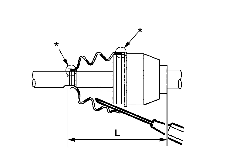
CAUTION:
If grease adheres to boot mounting surface (indicated by “*” marks) on shaft or joint sub-assembly, boot may come off. Remove all grease from boot mounting surface.
Make sure boot installation length (L) is specified length. Insert a suitable tool into the large end of boot. Bleed air from boot to prevent boot deformation.
| Boot installation length (L) | : Refer to Drive Shaft. |
CAUTION:
-
Boot may break if boot installation length is not within standard value.
-
Be careful that suitable tool does not contact inside surface of boot.
Install new large and small boot bands securely using Tool.

| Tool number | : KV40107300 (J-51751) |
CAUTION:
Do not reuse boot band.
NOTE:
Secure boot band so that dimension (M) meets specification as shown.

| Dimension (M) | : Refer to Boot Bands. |
Attempt to rotate boot to check whether or not boot bands are securing boot. If boot is not secure, remove boot bands, reposition boot, and install new boot bands.
CAUTION:
Do not reuse boot bands.
Clean mating surface of wheel hub lock nut and wheel hub and bearing.
CAUTION:
Do not apply lubricating oil to these mating surfaces.
Clean mating surface of drive shaft (A) and wheel hub and bearing.

Insert drive shaft to wheel hub and bearing, and then temporarily tighten wheel hub lock nut.
CAUTION:
Do not reuse wheel hub lock nut.
Attach front strut to steering knuckle and tighten lower strut nuts to specification. Refer to Exploded View.
CAUTION:
Do not reuse lower strut nuts.
Tighten wheel hub lock nut to specified torque. Refer to Exploded View.
CAUTION:
Do not use a power tool to tighten wheel hub lock nut.
Install nut retainer (2) and a new cotter pin (1); securely bend cotter pin to prevent rattles.

CAUTION:
-
Do not reuse cotter pin.
-
Bend cotter pin securely to prevent any looseness.
Install front wheel sensor to steering knuckle. Refer to Exploded View.
CAUTION:
-
Before installing, make sure there is no foreign material, such as iron fragments, adhered to pick-up part of front wheel sensor.
-
When installing, make sure there is no foreign material, such as iron fragments, on and in hole in steering knuckle for front wheel sensor. Make sure no foreign material has been caught in sensor rotor. Remove any foreign material and then install front wheel sensor.
Install disc brake rotor. Refer to Removal and Installation.
INSPECTION AND ADJUSTMENT AFTER INSTALLATION
Check wheel alignment. Refer to Inspection.
Adjust neutral position of the steering angle sensor. Refer to Description.
 Front Drive Shaft Boot
Exploded View
LH 1.
Shaft with damper
2.
Circular clip
3.
Dust shield
4.
Housing
5.
Snap ring
6.
Spider assembly
7.
Stopper ring
8...
 Transaxle Side
Removal and Installation
REMOVALRemove drive shaft. Refer to Removal and Installation (LH) (LH) or Removal and Installation (RH) (RH).
Secure front drive shaft in a vise...
Other information:
Nissan Murano (Z52) 2015-2024 Service Manual: Front Suspension :: Preparation. Preparation
Special Service Tool The actual shape of the tools may differ from those illustrated here. Tool number (TechMate No.) Tool name Description ST35652000 ( — ) Strut attachment Securing strut outer tube in a vise while disassembling and assembling front coil spring and strut...
Nissan Murano (Z52) 2015-2024 Owners Manual: Off-road recovery
While driving, the right side or left side wheels may unintentionally leave the road surface. If this occurs, maintain control of the vehicle by following the procedure below. Please note that this procedure is only a general guide. The vehicle must be driven as appropriate based on the conditions of the vehicle, road and traffic...
Categories
- Manuals Home
- Nissan Murano Owners Manual
- Nissan Murano Service Manual
- System malfunction
- Memory storage function (key-link)
- Vehicle Dynamic Control (VDC) OFF switch
- New on site
- Most important about car
Autolight system
The autolight system allows the headlights to turn on and off automatically. The autolight system can:
Turn on the headlights, front parking, tail, license plate and instrument panel lights automatically when it is dark. Turn off all the lights (except daylight running lights) when it is light. Keep all the lights on for a period of time after you place the ignition switch in the OFF position and all doors are closed.