Nissan Murano: Front Drive Shaft Boot / Transaxle Side
REMOVAL
Remove drive shaft. Refer to Removal and Installation (LH) (LH) or Removal and Installation (RH) (RH).
Secure front drive shaft in a vise.
CAUTION:
When securing shaft in a vise, always use copper or aluminum plates between vise and shaft.
Remove boot bands and slide boot back.
Put matching marks on housing and shaft before separating housing.
CAUTION:
Use paint or an equivalent for matching marks. Do not scratch surfaces.
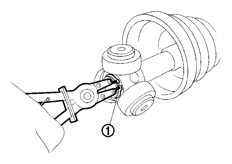
Remove stopper ring using a suitable tool.

Pull out housing.
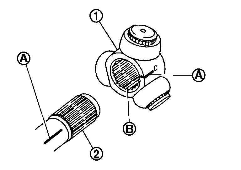
Put matching marks (A) on spider assembly and shaft.

CAUTION:
Use paint or an equivalent for matching marks. Do not scratch surfaces.
Remove snap ring (1) using a suitable tool.
Remove spider assembly from shaft.
Remove boot from shaft.
Remove circular clip from housing.
Remove dust shield from housing.
Clean old grease off slide joint housing.
INSPECTION AFTER REMOVAL
Shaft
Check shaft for cracks or damage. Replace entire drive shaft if necessary.
Housing and Spider Assembly
Check housing and spider assembly for scratches or wear. Replace entire drive shaft if necessary.
Boot
Check boot for cracks, damage, and leakage of grease. Replace boot if necessary.
INSTALLATION
Install new boot and new small boot band on shaft.

CAUTION:
-
Do not reuse boot and boot bands.
-
Cover drive shaft serration with protective tape (A) to prevent damage to boot during installation.
Remove protective tape wound around serrated part of shaft.
Align matching mark (A) on spider assembly (1) with matching mark on shaft (2). Install spider assembly to shaft with chamfer (B) facing shaft.
Secure spider assembly onto shaft with snap ring (1) using a suitable tool.
CAUTION:
Do not reuse snap ring.
Assemble housing onto spider assembly making sure to align matching marks made during disassembly, and fill with specified amount of new Genuine NISSAN Grease.
| Grease quantity | : Refer to Drive Shaft. |
 NOTE:
NOTE:
Always check with the Parts Department for the latest parts information.
Install new stopper ring to housing.
CAUTION:
Do not reuse stopper ring.
After installation, pull shaft to check engagement between housing and stopper ring.
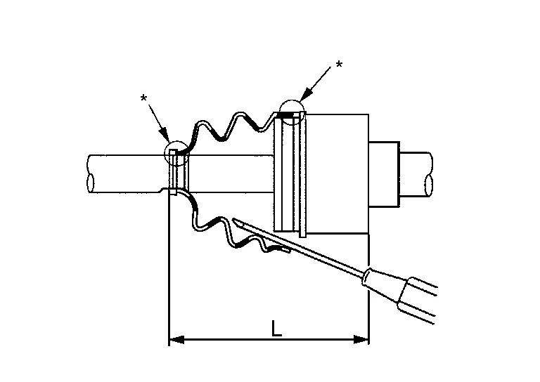
Install boot securely into grooves (indicated by "*" marks) as shown.
CAUTION:
If there is grease on boot mounting surfaces (indicated by "*" marks) on shaft or housing, boot may come off. Clean all grease from surfaces.
Make sure boot installation length (L) is length specified below. Insert a suitable tool into large end of boot. Bleed air from boot to prevent boot deformation.
| Boot installation length (L) | : Refer to Drive Shaft. |
CAUTION:
-
Boot may break if boot installation length is less than standard value.
-
Be careful that suitable tool does not contact inside surface of boot.
Install new large and small boot bands securely using Tool.

| Tool number | : KV40107300 (J-51751) |
CAUTION:
Do not reuse boot bands.
NOTE:
Secure boot band so that dimension (M) meets specification as shown.

| Dimension (M) | : Refer to Boot Bands. |
Install new dust shield to housing.
CAUTION:
Do not reuse dust shield.
Install new circular clip to housing.
CAUTION:
Do not reuse circular clip.
After installing housing and shaft, make sure boot position is correct. If boot position is not correct, remove old boot bands then reposition boot and secure with new boot bands.
CAUTION:
Do not reuse boot bands.
Install drive shaft. Refer to Removal and Installation (LH) (LH) or Removal and Installation (RH) (RH).
 Wheel Side
Removal and Installation
REMOVALRemove disc brake rotor. Refer to Removal and Installation.
Remove wheel sensor bolt (A) and position wheel sensor aside...
 Front Drive Shaft
Exploded View (LH)
1.
Drive shaft
2.
Nut retainer
3.
Cotter pin
Removal and Installation (LH)
REMOVALRemove disc brake rotor. Refer to Removal and Installation...
Other information:
Nissan Murano (Z52) 2015-2024 Service Manual: Wheel
Inspection Check tires for wear and improper inflation. Check wheels for deformation, cracks and other damage. If deformed, remove wheel and check wheel runout. Remove tire from wheel and mount wheel on a balancer machine. CAUTION: DO NOT use center hole cone-type clamping machines to hold wheel during tire removal/installation or balancing; damage to wheel paint, cladding or chrome may result...
Nissan Murano (Z52) 2015-2024 Owners Manual: Tire labeling
Example Federal law requires tire manufacturers to place standardized information on the sidewall of all tires. This information identifies and describes the fundamental characteristics of the tire and also provides the Tire Identification Number (TIN) for safety standard certification...
Categories
- Manuals Home
- Nissan Murano Owners Manual
- Nissan Murano Service Manual
- Passenger compartment
- Jacking up vehicle and removing the damaged tire
- Fuel recommendation
- New on site
- Most important about car
Seatback pockets

Theremaybe one or two seatback pockets located on the back of the driver and passenger seats. The pockets can be used to store maps.
WARNING