Nissan Murano: Front Axle :: Removal and Installation / Front Drive Shaft
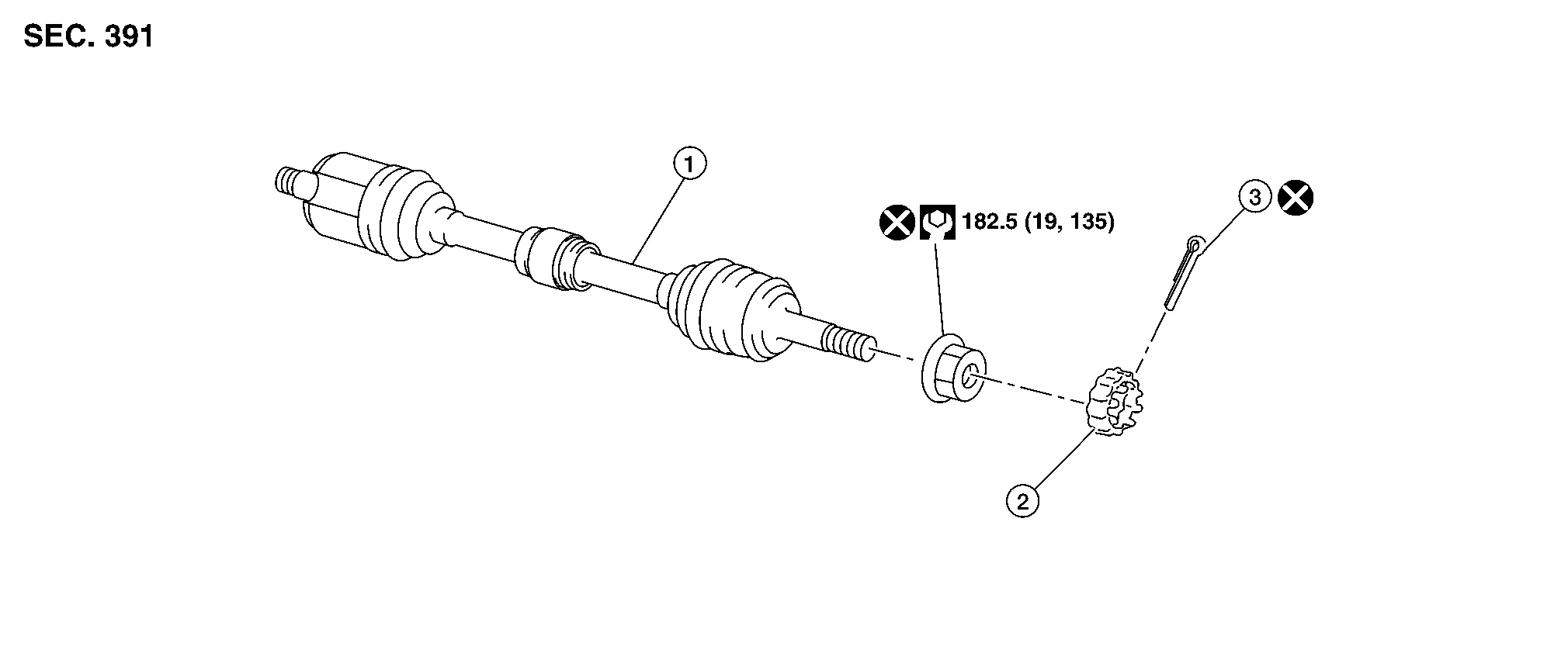
| 1. | Drive shaft | 2. | Nut retainer | 3. | Cotter pin |
REMOVAL
Remove disc brake rotor. Refer to Removal and Installation.
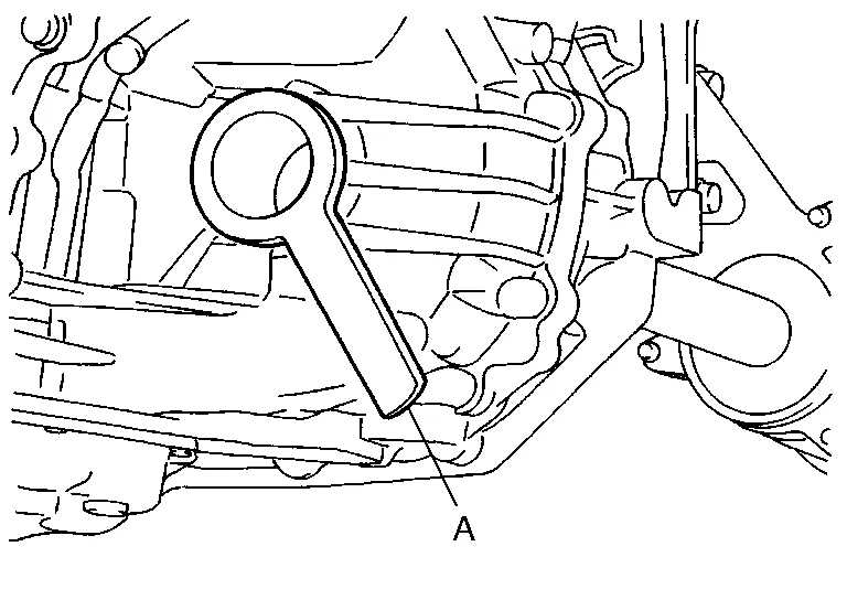
Remove wheel sensor bolt (A) and position wheel sensor aside. Refer to Exploded View.

CAUTION:
-
Failure to separate front wheel sensor from steering knuckle may result in damage to front wheel sensor.
-
Pull out front wheel sensor being careful to turn it as little as possible. Do not pull on front wheel sensor harness.
Remove cotter pin.
Remove nut retainer.
Loosen wheel hub lock nut from drive shaft using power tool.
Using a piece of wood and a suitable tool, tap on wheel hub lock nut to disengage drive shaft from wheel hub and bearing.

CAUTION:
-
Do not place drive shaft joint at an extreme angle. Be careful not to over-extend slide joint.
-
Do not allow drive shaft to hang without support.
 NOTE:
NOTE:
Use suitable puller if drive shaft cannot be separated from wheel hub and bearing.
Remove wheel hub lock nut.
Remove lower strut bolts and nuts.
Separate front strut from steering knuckle. Refer to Exploded View.
Separate drive shaft from wheel hub and bearing. Reposition drive shaft aside with wire.
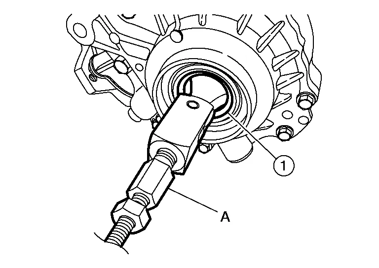
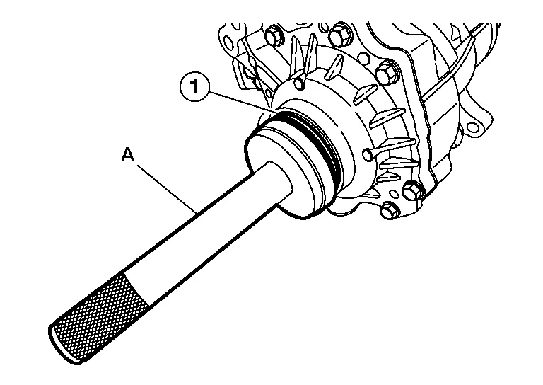
Set Tool (A)between drive shaft (slide joint side) and transaxle as shown. Remove drive shaft.
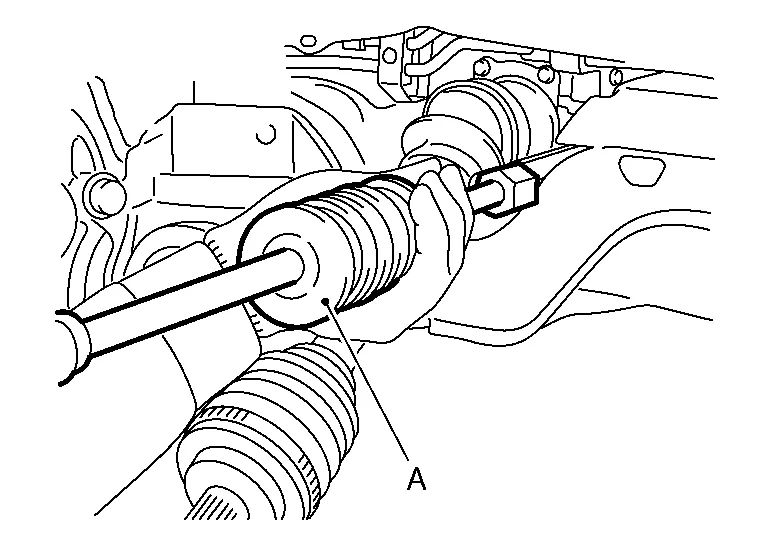
| Tool number | : Drive shaft joint puller (Commercially available) |
Remove differential side oil seal. Refer to Removal and Installation.
INSPECTION AFTER REMOVAL
-
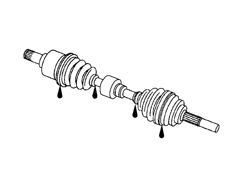
Move joint up/down, left/right, and in axial direction. Check for any rough movement or significant looseness.
-
Check boot for cracks or other damage and for grease leakage.
-
If damaged, disassemble drive shaft to verify damage, and repair or replace as necessary.
INSTALLATION
Install new differential side oil seal. Refer to Removal and Installation.
CAUTION:
Do not reuse differential side oil seal.
Install new circular clip on drive shaft in circular clip groove on transaxle side. Refer to Exploded View (LH).
CAUTION:
-
Do not reuse circular clip.
-
Make sure new circular clip on drive shaft is securely fastened.
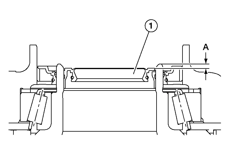
In order to prevent damage to differential side oil seal, place Tool (A) onto oil seal before inserting drive shaft as shown. Slide drive shaft into slide joint and tap with a suitable tool to install securely.
| Tool number | : KV38107900 (J–52469–1) |
WARNING:
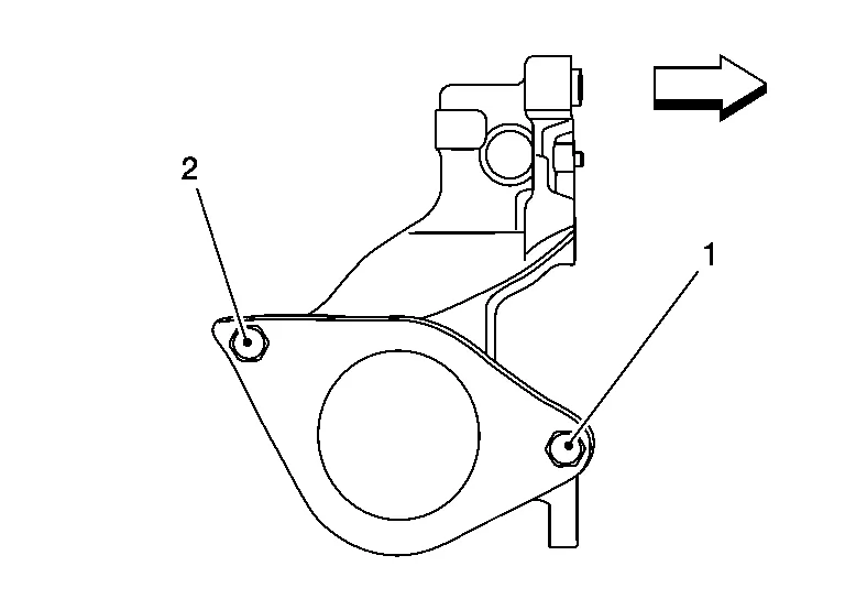
Ensure that circular clip is properly engaged, otherwise the joint subassembly could pull away from transaxle during Nissan Murano vehicle operation resulting in loss of drive force and possible drive shaft damage, which may cause a crash and serious injury or damage the drive shaft.
-
To ensure the circular clip is properly engaged, grasp the housing (1) and pull back and forth in axial direction while listening for clicking sounds.
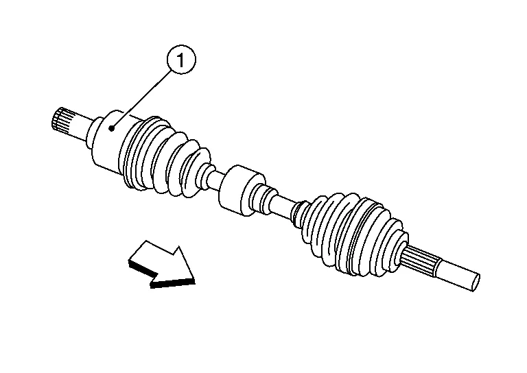
-
Pull the joint sub-assembly in the axial direction away from transaxle assembly (arrow). Confirm that the joint sub assembly cannot be pulled out.
Clean mating surfaces of wheel hub lock nut and wheel hub and bearing.
CAUTION:
Do not apply lubricating oil to these mating surfaces.
Tighten wheel hub lock nut to specification. Refer to Exploded View (LH).
CAUTION:
-
Do not reuse wheel hub lock nut.
-
Do not use a power tool to tighten wheel hub lock nut.
When installing cotter pin (1) and nut retainer (2), securely bend cotter pin to prevent rattles.

CAUTION:
Do not reuse cotter pin.
Remainder of installation is in reverse order of removal.
INSPECTION AND ADJUSTMENT AFTER INSTALLATION
Check CVT fluid level and leakage. Refer to Inspection.
Check wheel alignment. Refer to Inspection.
Adjust neutral position of the steering angle sensor. Refer to Description.
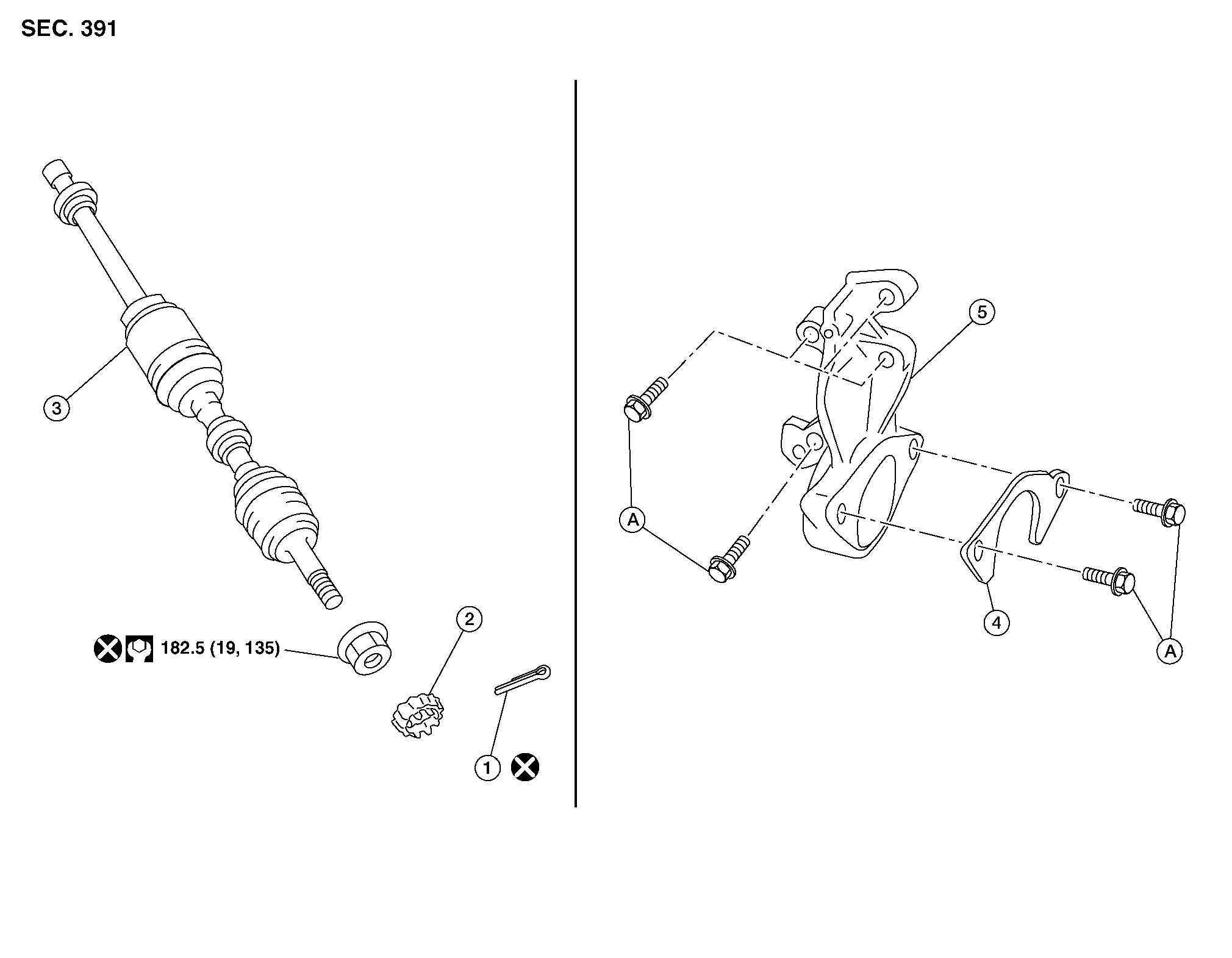
| 1. | Cotter pin | 2. | Nut retainer | 3. | Drive shaft |
| 4. | Bearing retainer | 5. | Support bearing bracket | A. | Refer to Removal and Installation. |
REMOVAL
Remove disc brake rotor. Refer to Removal and Installation.
Remove wheel sensor bolt (A) and position wheel sensor aside. Refer to Exploded View.
CAUTION:
-
Failure to separate front wheel sensor from steering knuckle may result in damage to front wheel sensor.
-
Pull out front wheel sensor being careful to turn it as little as possible. Do not pull on front wheel sensor harness.
Remove cotter pin.
Remove nut retainer.
loosen wheel hub lock nut from drive shaft using power tool.
Using a piece of wood and a suitable tool, tap on wheel hub lock nut to disengage drive shaft from wheel hub and bearing.
CAUTION:
-
Do not place drive shaft joint at an extreme angle. Be careful not to over-extend slide joint.
-
Do not allow drive shaft to hang without support.
NOTE:
Use suitable puller if drive shaft cannot be separated from wheel hub and bearing.
Remove wheel hub lock nut.
Remove lower strut bolts and nuts.
Separate front strut from steering knuckle. Refer to Exploded View.
Remove bearing retainer to support bearing bracket bolts.
Remove bearing retainer.
Set Tool (A) between drive shaft (slide joint side) and transaxle as shown. Remove drive shaft.
CAUTION:
Do not place drive shaft joint at an extreme angle when removing drive shaft. Also be careful not to over-extend slide joint.
| Tool number (A) | : Drive shaft joint puller (Commercially available) |
If necessary, remove support bearing bracket bolts and bracket.
For AWD models, remove the drive shaft oil seal using the following procedure:Remove the bolts and the support bearing bracket. Using a suitable tool, remove the transfer cover oil seal.
CAUTION:
-
When removing transfer cover oil seal with suitable tool, do not damage the transfer cover.
-
Do not reuse transfer cover oil seal.
CAUTION:
Do not reuse drive shaft oil seal.
For FWD Nissan Murano vehicles, remove differential side oil seal. Refer to Removal and Installation.
INSPECTION AFTER REMOVAL
-
Move joint up/down, left/right, and in axial direction. Check for any rough movement or significant looseness.
-
Check boot for cracks or other damage and for grease leakage.
-
If damaged, disassemble drive shaft to verify damage, and repair or replace as necessary.
INSTALLATION
For AWD models, install the drive shaft oil seal and transfer cover oil seal using the following procedure:Install drive shaft oil seal (1) onto Tool (A) before installing into transfer case assembly using Tool (B).
CAUTION:
Do not reuse drive shaft oil seal.
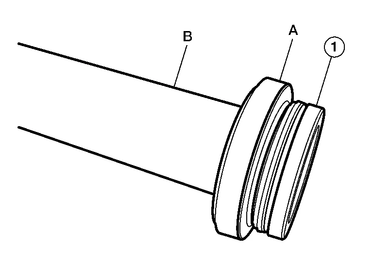
| Tool (A) | : — (J-52390) |
| Tool (B) | : — (J-8092) |
| Dimension (A) | : 2.0 - 2.6 mm (0.079 - 0.102 in) |
CAUTION:
Do not reuse transfer cover oil seal.
Verify the transfer cover oil seal (2) is installed to the correct depth (A).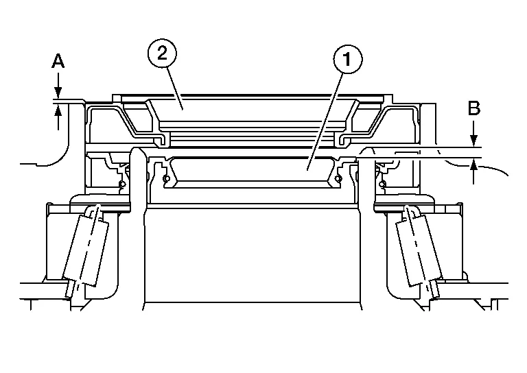
| Dimension (A) | : 0.0 - 0.6 mm (0.000 - 0.024 in) |
| (1) | : Drive shaft oil seal |
| (B) | : Drive shaft oil seal installation depth |
Install support bearing bracket.
-
Tighten support bearing bracket bolts in numerical order as shown.
-
Refer to following for installation positions of bolts.
| M10 bolt | No. 1 - 4: | 48.0 N·m (4.9 kg-m, 35 ft-lb) |
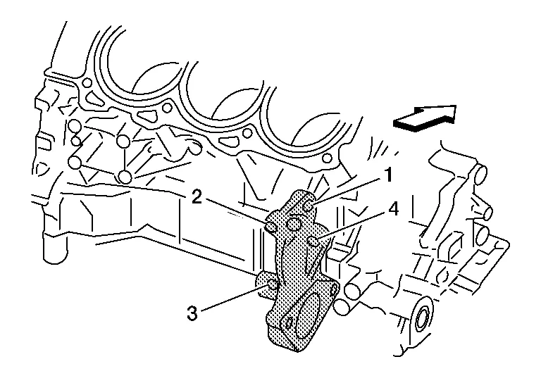
| : Front |
For FWD models, install a new differential side oil seal. Refer to Removal and Installation.
CAUTION:
Do not reuse differential side oil seal.
Install new circular clip on drive shaft in circular clip groove on transaxle side. Refer to Exploded View (RH).
CAUTION:
-
Do not reuse circular clip.
-
Make sure new circular clip on drive shaft is securely fastened.
In order to prevent damage to differential side oil seal, place Tool (A) onto oil seal before inserting drive shaft as shown. Slide drive shaft into slide joint and tap with a hammer to install securely.
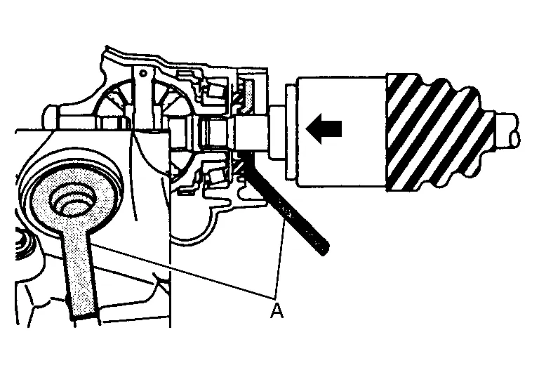
| Tool number | : KV38107900 (J–52469–1) |
WARNING:
Ensure that circular clip is properly engaged, otherwise the joint subassembly could pull away from transaxle during Nissan Murano vehicle operation resulting in loss of drive force and possible drive shaft damage, which may cause a crash and serious injury or damage the drive shaft.
-
To ensure the circular clip is properly engaged, grasp the housing (1) and pull back and forth in axial direction while listening for clicking sounds.
-
Pull the joint sub-assembly in the axial direction away from transaxle assembly (arrow). Confirm that the joint sub assembly cannot be pulled out.
Install bearing retainer.
-
Tighten bearing retainer bolts in numerical order shown.
| M8 bolt | No. 1 and No. 2: | 25.0 N·m (2.6 kg-m, 18 ft-lb) |
| : Front |
Clean mating surfaces of wheel hub lock nut and wheel hub and bearing.
CAUTION:
Do not apply lubricating oil to these surfaces.
Tighten wheel hub lock nut to specification. Refer to Exploded View (RH).
CAUTION:
-
Do not reuse wheel hub lock nut.
-
Do not use power tools to tighten wheel hub lock nut.
When installing cotter pin (1) and nut retainer (2), securely bend cotter pin to prevent rattles.
CAUTION:
Do not reuse cotter pin.
Installation of remaining components is in reverse order of removal.
INSPECTION AND ADJUSTMENT AFTER INSTALLATION
-
For FWD vehicles, check CVT fluid level and leakage. Refer to Inspection.
-
For AWD Nissan Murano vehicles, check transfer case fluid level. Refer to Inspection.
-
Check wheel alignment. Refer to Inspection.
-
Adjust neutral position of the steering angle sensor. Refer to Description.
 Transaxle Side
Removal and Installation
REMOVALRemove drive shaft. Refer to Removal and Installation (LH) (LH) or Removal and Installation (RH) (RH).
Secure front drive shaft in a vise...
 Front Axle :: Unit Disassembly and Assembly. Front Drive Shaft
Exploded View (LH)
1.
Shaft with damper
2.
Circular clip
3.
Dust shield
4.
Housing
5.
Snap ring
6.
Spider assembly
7.
Stopper ring
8...
Other information:
Nissan Murano (Z52) 2015-2024 Owners Manual: Operating range
The Intelligent Key functions can only be used when the Intelligent Key is within the specified operating range. When the Intelligent Key battery is almost discharged or strong radio waves are present near the operating location, the Intelligent Key system’s operating range becomes narrower and may not function properly...
Nissan Murano (Z52) 2015-2024 Service Manual: Engine Lubrication System :: System Description. Lubrication System
Engine Lubrication System 1. Camshaft (EXH) journal (No. 1) 2. Timing chain tensioner (secondary) 3. Camshaft (EXH) 4. Camshaft (INT) journal (No. 2) 5. Camshaft (INT) 6. Cylinder head (bank 2) 7. Main oil gallery 8. Upper oil pan 9...
Categories
- Manuals Home
- Nissan Murano Owners Manual
- Nissan Murano Service Manual
- Memory storage function (key-link)
- System malfunction
- Jacking up vehicle and removing the damaged tire
- New on site
- Most important about car
Unfastening the seat belts. Checking seat belt operation
Unfastening the seat belts

To unfasten the seat belt, press the button
on the buckle  . The seat belt
automatically
retracts.
. The seat belt
automatically
retracts.