Nissan Murano: Steering System :: Removal and Installation / Steering Gear and Linkage
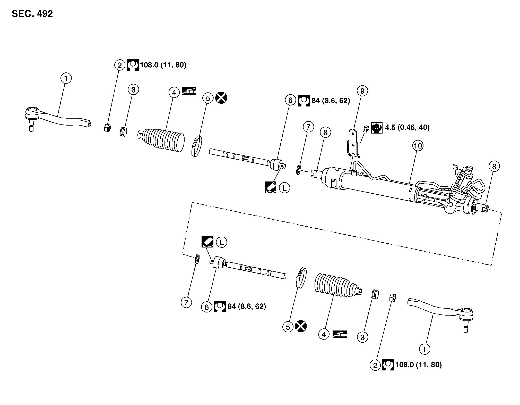
| 1. | Outer socket | 2. | Inner socket lock nut | 3. | Small boot clamp |
| 4. | Boot | 5. | Large boot clamp | 6. | Inner socket |
| 7. | Spacer | 8. | Rack bar (not serviceable) | 9. | Bracket |
| 10. | Steering gear |
REMOVAL
Remove front wheel and tire using power tool.
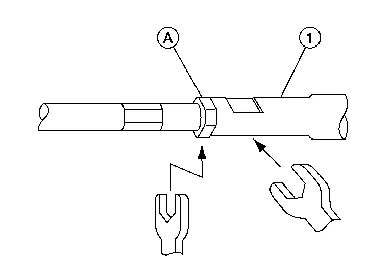
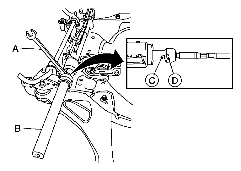
Loosen inner socket lock nut (A).
CAUTION:
To prevent damage, hold outer socket (1) across flats using suitable tool while loosening inner socket lock nut (A).
Remove cotter pin from outer socket.
Loosen outer socket nut and separate outer socket from steering knuckle using suitable tool.
CAUTION:
Leave the outer socket nut half threaded on the outer socket to prevent damage to threads and to prevent the suitable tool from coming off suddenly.
Remove outer socket nut and outer socket.
INSTALLATION
Install outer socket to inner socket.
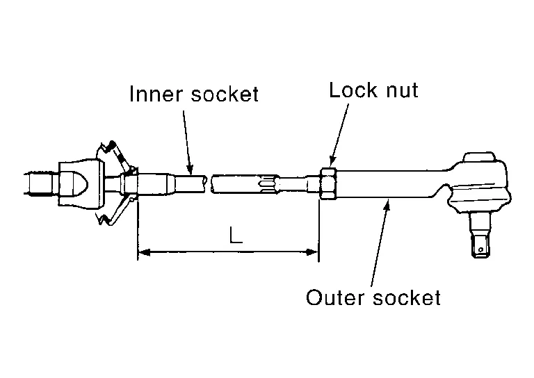
Adjust inner socket to standard length (L), and then tighten inner socket lock nut to the specified torque. Refer to Exploded View. Check length of inner socket (L) again after tightening inner socket lock nut. Make sure that the length is the standard.
| Inner socket length (L) | : Refer to Steering Gear. |
CAUTION:
-
To prevent damage, hold outer socket across flats using suitable tool while tightening inner socket lock nut.
-
Adjust toe-in after this procedure. The length achieved after toe-in adjustment is not necessarily the above value.
-
Inspect to make sure no boot deformation has occurred during toe-in adjustment. Adjust boot as necessary.
Install outer socket to steering knuckle.
Install outer socket nut to outer socket. Refer to Exploded View.
Install cotter pin to outer socket stud hole.
WARNING:
After torquing the outer socket nut, be sure to install the cotter pin through the outer socket stud hole and bend the cotter pin around the outer socket stud.
CAUTION:
Do not reuse cotter pin.
Install front wheel and tire. Refer to Removal and Installation.
Check wheel alignment. Refer to Wheel Alignment (Unladen1).
Adjust the neutral position of the steering angle sensor. Refer to Description.
REMOVAL
Remove outer socket. Refer to Removal and Installation - Outer socket.
Remove inner socket lock nut.
Remove small boot clamp and large boot clamp.
CAUTION:
Do not reuse large boot clamp.
Remove boot.
INSTALLATION
Install large end of boot (1) to gear housing.
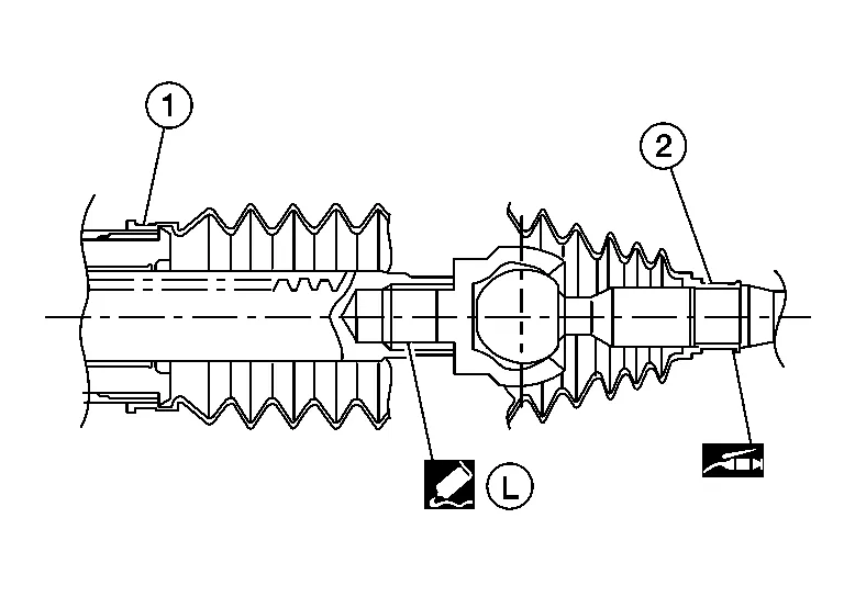
Apply silicone grease between the inner socket and small end of boot (2). Install small end of boot to inner socket boot mounting groove.
CAUTION:
To prevent boot deformation or damage during toe-in adjustment, apply silicone grease between the inner socket and small end of boot.
Install small boot clamp.

Install large boot clamp using Tool.
CAUTION:
Do not reuse large boot clamp.
| Tool number | : KV40107300 (J-51751) |
Partially thread the inner socket lock nut on the inner socket.
Install the outer socket. Refer to Removal and Installation - Outer socket.
Check wheel alignment. Refer to Wheel Alignment (Unladen1).
Adjust the neutral position of the steering angle sensor. Refer to Description.
REMOVAL
Remove boot. Refer to Removal and Installation - Boot.
Remove inner socket.
CAUTION:
To prevent damage to the rack bar when removing the inner socket, hold suitable tool (A) across rack bar flats (C) while turning suitable tool (B) across inner socket flats (D).
Remove spacer.
INSTALLATION
Place spacer on the end of the rack bar.
Apply medium strength thread locker to threads of inner socket. Tighten inner socket to the specified torque. Refer to Exploded View.
CAUTION:
To prevent damage to the rack bar when installing the inner socket, hold suitable tool (A) across rack bar flats (C) while turning suitable tool (B) across inner socket flats (D).
Install boot. Refer to Removal and Installation - Boot.
Check wheel alignment. Refer to Wheel Alignment (Unladen1).
Adjust the neutral position of the steering angle sensor. Refer to Description.
 Steering Column
Exploded View
Electric steering column 1.
Steering column
2.
Hole cover
3.
Lower boot
4.
Steering intermediate shaft
Mechanical steering column 1...
 Power Steering Oil Pump
Exploded View
1.
Power steering reservoir cap
2.
Power steering oil pump
3.
Low-pressure piping
4.
High-pressure piping
Front
Removal and Installation
WARNING:
Power steering pump outer shell will be hot while running and after driving...
Other information:
Nissan Murano (Z52) 2015-2024 Service Manual: Low Tire Pressure Warning Lamp
Component Function Check CHECK THE ILLUMINATION OF THE LOW TIRE PRESSURE WARNING LAMP Check that the low tire pressure warning lamp is turned OFF after illuminating for approximately 1 second, when the ignition switch is placed ON. Is the inspection result normal? YES>> Inspection End...
Nissan Murano (Z52) 2015-2024 Service Manual: U1000-01 Can Comm Circuit
DTC Description CAN COMMUNICATIONCAN (Controller Area Network) is a serial communication line for real time applications. It is an on-Nissan Murano vehicle multiplex communication line with high data communication speed and excellent error detection ability...
Categories
- Manuals Home
- Nissan Murano Owners Manual
- Nissan Murano Service Manual
- Checking engine oil level
- Intelligent Forward Collision Warning (I-FCW)
- Shift lock release
- New on site
- Most important about car
Fuel gauge

The gauge indicates the approximate fuel level in the tank.
The gauge may move slightly during braking, turning, acceleration, or going up or down hills.
The gauge needle returns to 0 (Empty) after the ignition switch is placed in the OFF position.