Nissan Murano: Back Door Lock / Spindle Unit
REMOVAL
Support back door using a suitable tool.
WARNING:
Bodily injury may occur if back door is not supported properly when removing back door spindle unit.
Remove luggage side upper finisher. Refer to Removal and Installation.
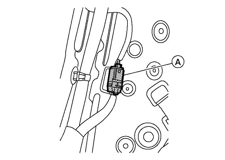
Disconnect the harness connector (A) from the spindle unit.
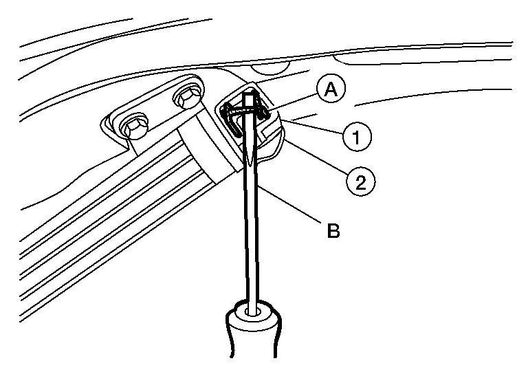
Remove metal clip (A) from spindle unit upper hinge ball socket (1) using a suitable tool (B) and release spindle unit from spindle unit upper hinge (2).
Remove metal clip from spindle unit lower hinge ball socket using a suitable tool and release spindle unit.
Pull harness through Nissan Murano vehicle body and remove spindle unit.
INSTALLATION
Installation is in the reverse order of removal.
CAUTION:
-
When reusing stud ball, always apply locking sealant before installing stud ball to back door.
-
After installation, check back door open/close and lock/unlock operation.
-
Perform calibration of automatic back door position information. Refer to Description.
 NOTE:
NOTE:
Check spindle unit grommet lubrication condition. if necessary, apply a suitable lubrication to spindle unit grommet during installation.
 Door Lock
Exploded View
1.
Back door stay [(LH/RH) (without automatic back door)]
2.
Spindle unit [(LH/RH) (with automatic back door)]
3.
Back door touch sensor [(LH) (with automatic back door)]
4...
 Back Door Stay
Removal and Installation
REMOVALSupport back door using a suitable tool.
WARNING:
Bodily injury may occur if no supporting rod is holding back door open when removing back door stay...
Other information:
Nissan Murano (Z52) 2015-2024 Owners Manual: Conditions the Remote Engine Start will notwork
The Remote Engine Start will not operate if any of the following conditions are present: The ignition switch is placed in the ON position. The hood is not securely closed. The hazard indicator lights are on. The engine is still running. The engine must be completely stopped...
Nissan Murano (Z52) 2015-2024 Service Manual: B2196 Dongle Ng
DTC Description BCM performs ID verification between BCM and dongle unit.When verification result is OK, BCM permits cranking.DTC DETECTION LOGICNOTE: If DTC B2196 is displayed with DTC U1000, first perform the trouble diagnosis for DTC U1000. Refer to DTC Description...
Categories
- Manuals Home
- Nissan Murano Owners Manual
- Nissan Murano Service Manual
- System malfunction
- Settings
- Checking engine oil level
- New on site
- Most important about car
Unfastening the seat belts. Checking seat belt operation
Unfastening the seat belts

To unfasten the seat belt, press the button
on the buckle  . The seat belt
automatically
retracts.
. The seat belt
automatically
retracts.