Nissan Murano: Back Door Lock / Back Door Stay
REMOVAL
Support back door using a suitable tool.
WARNING:
Bodily injury may occur if no supporting rod is holding back door open when removing back door stay.
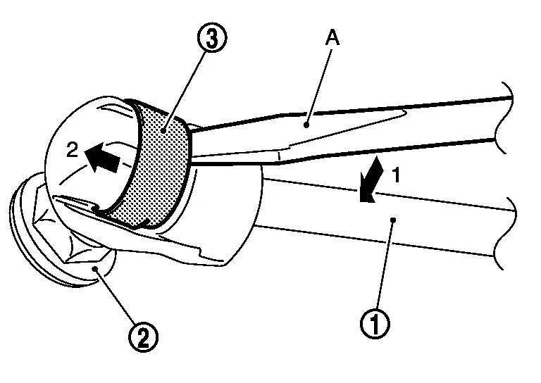
Release metal clip (3) located on connection between back door stay (1) and stud ball (back door side) (2) using a suitable tool (A).
Remove back door stay (back door side).
Repeat procedure for removing back door stay from body side.
INSTALLATION
Installation is in the reverse order of removal.
CAUTION:
After installation, check back door open/close operation.
 Spindle Unit
Removal and Installation
REMOVALSupport back door using a suitable tool.
WARNING:
Bodily injury may occur if back door is not supported properly when removing back door spindle unit...
 Back Door Touch Sensor
Removal and Installation
CAUTION:
Use care not to bend touch sensor.
Replace the back door touch sensor if it has been dropped or sustained an impact...
Other information:
Nissan Murano (Z52) 2015-2024 Owners Manual: Wheel balance
Unbalanced wheels may affect vehicle handling and tire life. Even with regular use, wheels can get out of balance. Therefore, they should be balanced as required. Wheel balance service should be performed with the wheels off the vehicle. Spin balancing the wheels on the vehicle could lead to mechanical damage...
Nissan Murano (Z52) 2015-2024 Service Manual: Headlamp (hi) Circuit
Component Function Check CHECK HEADLAMP (HI) OPERATION CONSULT Select “EXTERNAL LAMPS” in “Active Test” mode of “IPDM E/R”. While operating the test items, check that the headlamp (HI) blinks. Hi : Headlamp (HI) blinks (ON/OFF is repeated 1 second each)...
Categories
- Manuals Home
- Nissan Murano Owners Manual
- Nissan Murano Service Manual
- Rear bench seat adjustment
- Indicator lights
- Intelligent Forward Collision Warning (I-FCW)
- New on site
- Most important about car
Luggage hooks

When securing items using luggage hooks located on the back of the seat or side finisher do not apply a load over more than 6.5 lbs. (29 N) to a single hook.
The luggage hooks that are located on the floor should have loads less than 110 lbs. (490 N) to a single hook.