Nissan Murano: Sonar System :: Removal and Installation / Sonar Sensor
REAR SONAR SENSOR OUTER
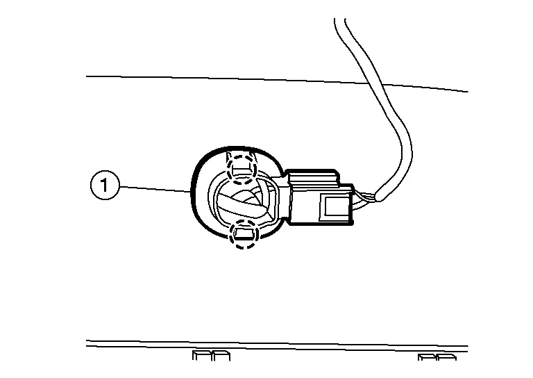
Release pawls using suitable tool and remove rear sonar sensor (1).
 NOTE:
NOTE:
Rear sonar sensor (inner) shown, rear sonar sensor (outer) similar.
 |
:Pawl |
Disconnect the harness connector from rear sonar sensor.
Remove the rear sonar sensor finisher from the rear bumper fascia (if necessary).
CAUTION:
If the rear sonar sensor finisher is replaced, clean area before installation.
Installation is in the reverse order of removal.
REAR SONAR SENSOR INNER
Remove rear bumper fascia. Refer to Exploded View.
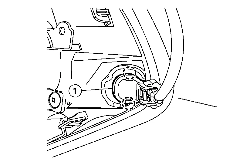
Release pawls using suitable tool and remove rear sonar sensor (1).
|
:Pawl |
Disconnect the harness connector from rear sonar sensor.
Remove the rear sonar sensor finisher from the rear bumper fascia (if necessary).
CAUTION:
If the rear sonar sensor finisher is replaced, clean area before installation.
Installation is in the reverse order of removal.
FRONT SONAR SENSOR OUTER
Partially remove front portion of front fender protector. Refer to Exploded View.
Release pawls using suitable tool and remove front sonar sensor (1).
|
:Pawl |
Disconnect the harness connector from front sonar sensor.
Remove the front sonar sensor finisher from the front bumper fascia (if necessary).
CAUTION:
If the front sonar sensor finisher is replaced, clean area before installation.
Installation is in the reverse order of removal.
FRONT SONAR SENSOR INNER
Remove front under cover. Refer to Removal and Installation.
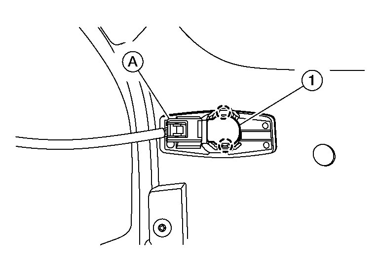
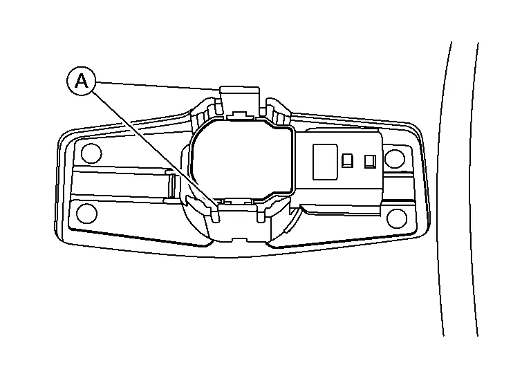
Disconnect the harness connector (A) from the front sonar sensor inner (1).
|
:Pawl |
Using a suitable tool, release pawls from the front sonar sensor inner and remove.
Remove the front sonar sensor finisher from the bumper fascia (if necessary).
CAUTION:
Verify that the connector direction is within the specification shown when assembling the bumper fascia.
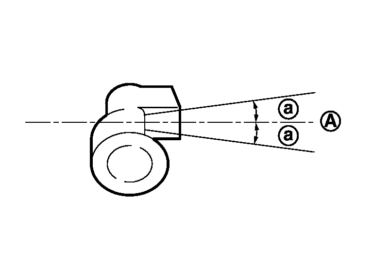
| (A) | : Horizontal position |
| (a) | : ± 10° |
Install front sonar sensor inner to sensor finisher.
Degrease and clean the inner side of the front bumper fascia and apply adhesion promoter to the area shown (A).
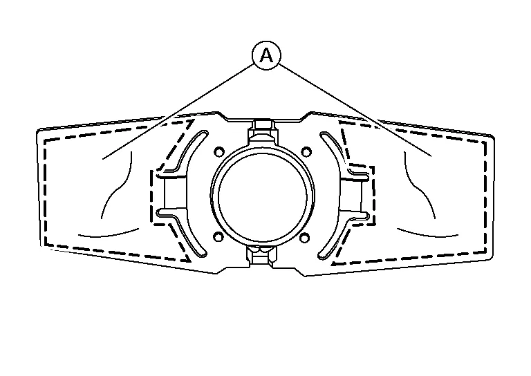
Let the adhesion promoter dry for more than three minutes and peel off the double sided tape film, and then taking precautions not to contact the bumper with the double sided tape (A), bend the front sonar sensor inner finisher in the direction shown.
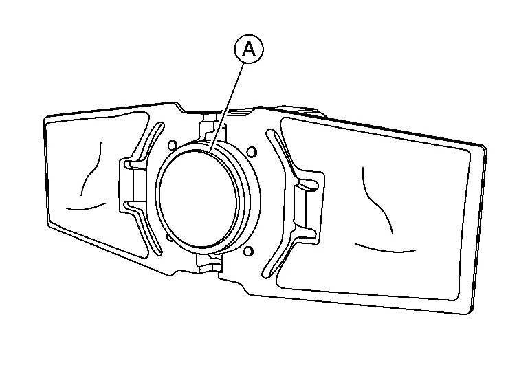
Match the part of the front sonar sensor inner (A) shown in the figure to the sensor installing hole of the front bumper fascia.
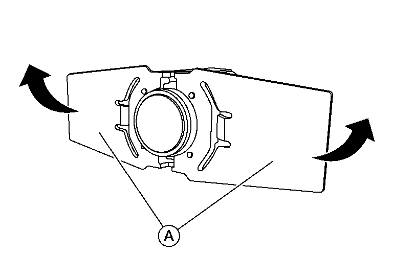
Remove the front sonar sensor inner from the sensor finisher and press the adhesion face (A) for more than two seconds to securely bond the front sonar sensor inner finisher to front bumper fascia inner.
| Target pressure | : 50.0 N (5.1 kg, 11.24 lb) |
CAUTION:
-
When temperature is less than 15°C (59°F), use a drier, etc., to warm the adhesion face and proceed.
-
After installing front sonar sensor inner finisher, do not move finisher for two - three hours.
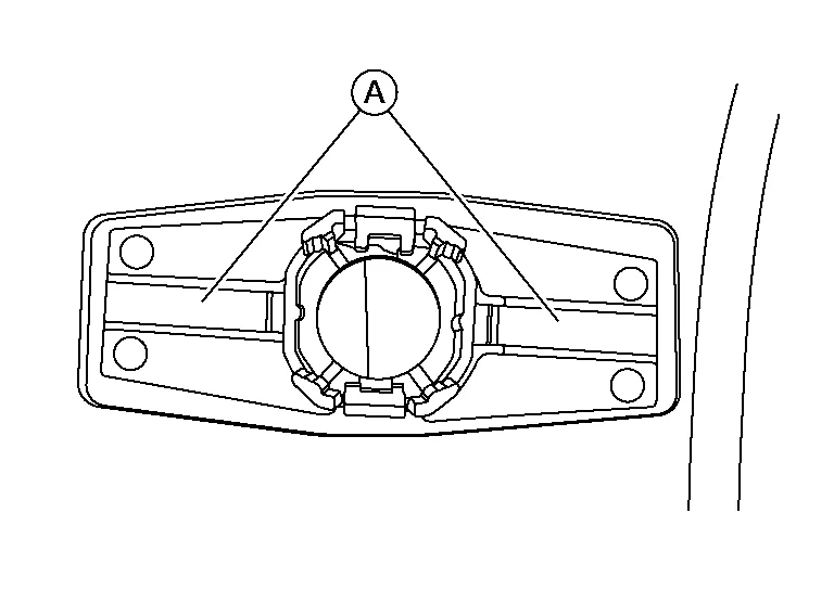
Install front sonar sensor inner to the sensor finisher.
Shake the part of the front sonar sensor inner finisher (A) up and down and then right and left to confirm that the finisher has been installed (bonded) firmly.
Connect the harness connector to the front sonar sensor inner.

 Sonar Buzzer
Removal and Installation
REMOVALRemove instrument lower panel LH. Refer to Removal and Installation.
Disconnect harness connector from the sonar buzzer...
Other information:
Nissan Murano (Z52) 2015-2024 Service Manual: B1321 Front Right Tweeter
DTC Description DTC DETECTION LOGIC DTC No. CONSULT screen terms (Trouble diagnosis content) DTC detection condition B1321–13 Front right tweeter (Instrument panel tweeter RH) [OPEN] Diagnosis condition When ignition switch is ON. Signal (terminal) FR SP RH+ (terminal 11) FR SP RH− (terminal 12) Threshold – Diagnosis delay time 30 seconds or more POSSIBLE CAUSE FR SP RH+ open FR SP RH− open Instrument panel tweeter RH AV control unit FAIL-SAFEInstrument panel tweeter RH inoperative Confirmation Procedure PERFORM DTC CONFIRMATION PROCEDURE CONSULT Ignition switch ON...
Nissan Murano (Z52) 2015-2024 Service Manual: Configuration (adas Control Unit)
Description Since vehicle specifications are not included in the ADAS control unit after replacement, it is required to write Nissan Murano vehicle specifications using CONSULT. Configuration has three functions as follows: Function Description Read/Write Configuration Before ECU Allows the reading of Nissan Murano vehicle specification written in ADAS control unit to store the specification in CONSULT...
Categories
- Manuals Home
- Nissan Murano Owners Manual
- Nissan Murano Service Manual
- Warning lights
- Memory storage function (key-link)
- Rear bench seat adjustment
- New on site
- Most important about car
Seatback pockets

Theremaybe one or two seatback pockets located on the back of the driver and passenger seats. The pockets can be used to store maps.
WARNING