Nissan Murano: Engine Mechanical :: Removal and Installation / Rocker Cover
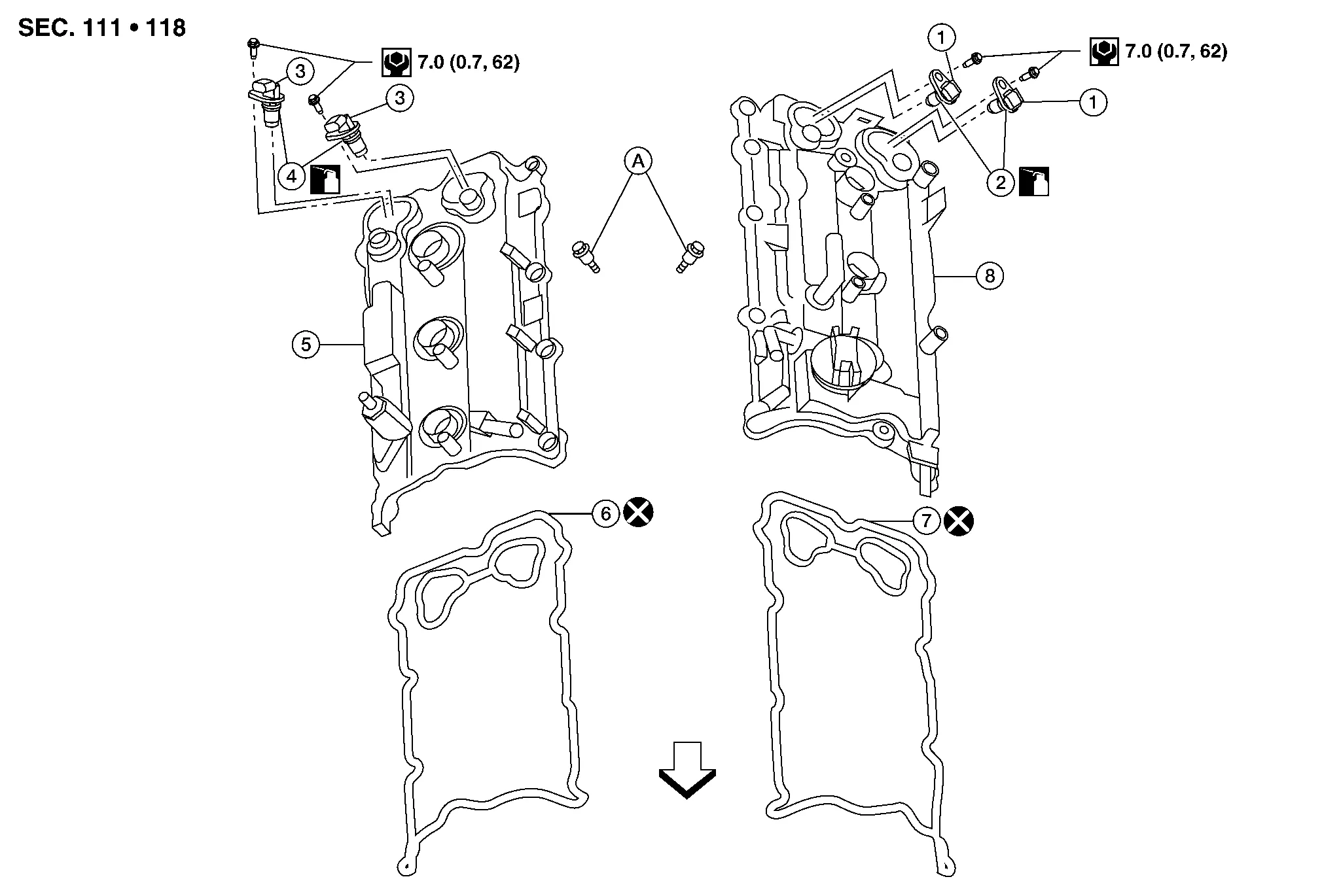
| 1. | Camshaft position sensor (Bank 2) | 2. | O-rings | 3. | Camshaft position sensor (Bank 1) |
| 4. | O-rings | 5. | Rocker cover (Bank 1) | 6. | Rocker cover gasket (Bank 1) |
| 7. | Rocker cover gasket (Bank 2) | 8. | Rocker cover (Bank 2) | A. | Refer to Removal and Installation (bank 1) or Removal and Installation (bank 2). |
| Engine front |
REMOVAL
Remove the engine room cover. Refer to Removal and Installation.
Disconnect the harness connector from air fuel ratio sensor 1 (bank 2).
Remove blow by hose from rocker cover.
Remove camshaft position sensors.
CAUTION:
-
Handle carefully to avoid dropping and shocks.
-
Do not disassemble camshaft position sensor.
-
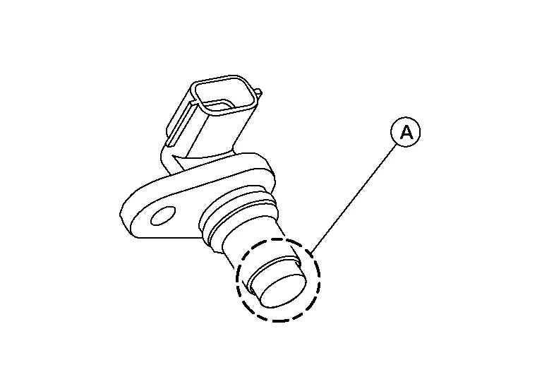
Do not allow metal powder to adhere to magnetic part at sensor tip (A).
-
Do not place sensors in a location where they are exposed to magnetism.
Unclip the camshaft position sensor harness retainers.
Remove the ignition coils. Refer to Removal and Installation (bank 2).
CAUTION:
Do not shock ignition coils.
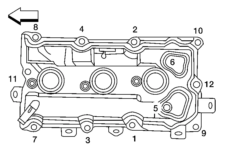
Remove rocker cover bolts from cylinder head in the reverse order shown.
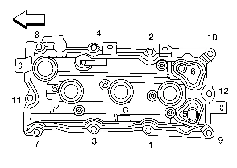
| : Engine front |
Remove the rocker cover and gasket.
Remove the oil filler cap from the rocker cover (if necessary).
INSTALLATION
Installation is in the reverse order of removal.
CAUTION:
-
Do not reuse rocker cover gasket.
-
Blow by hose clamps should be installed facing upwards.
-
Install press fit hoses so that the white mark faces the rib of the connector.
-
Apply sealant to the areas on the front corners using suitable tool.
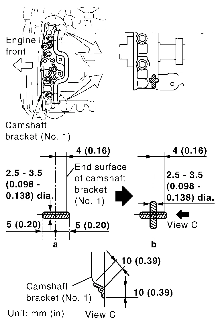
-
Use Genuine Silicone RTV Sealant or equivalent. Refer to Recommended Chemical Products and Sealants.
CAUTION:
-
Installation should be done within 5 minutes after applying liquid gasket.
-
Do not fill the engine with engine oil for at least 30 minutes after the components are installed to allow the sealant to cure.
-
-
Tighten the rocker cover bolts to specification in two steps in order shown.

: Engine front Rocker cover bolts Step 1 : 1.96 N·m (0.20 kg-m, 17 in-lb) Step 2 : 8.33 N·m (0.85 kg-m, 74 in-lb)
REMOVAL
Remove the engine room cover. Refer to Removal and Installation.
Disconnect the harness connector from air fuel ratio sensor 1 (bank 1).
Remove the front air duct and air duct hose and resonator assembly. Refer to Removal and Installation.
Remove the intake manifold collector. Refer to Removal and Installation.
Remove camshaft position sensors.
CAUTION:
-
Handle carefully to avoid dropping and shocks.
-
Do not disassemble camshaft position sensor.
-
Do not allow metal powder to adhere to magnetic part at sensor tip (A).
-
Do not place sensors in a location where they are exposed to magnetism.
Disconnect the PCV hose from the rocker cover.
Disconnect the ignition coil harness connectors.
Remove ignition coils. Refer to Removal and Installation (bank 1).
CAUTION:
Do not shock ignition coils.
Remove rocker cover bolts from cylinder head in the reverse order shown.
| : Engine front |
Remove the rocker cover and gasket.
INSTALLATION
Installation is in the reverse order of removal.
CAUTION:
-
Do not reuse rocker cover gasket.
-
Blow by hose clamps should be installed facing upwards.
-
Install press fit hoses so that the white mark faces the rib of the connector.
-
Apply sealant to the areas on the front corners using suitable tool.
-
Use Genuine Silicone RTV Sealant or equivalent. Refer to Recommended Chemical Products and Sealants.
CAUTION:
-
Installation should be done within 5 minutes after applying liquid gasket.
-
Do not fill the engine with engine oil for at least 30 minutes after the components are installed to allow the sealant to cure.
-
-
Tighten the rocker cover bolts in two steps in order as shown.
: Engine front Rocker cover bolts Step 1 : 1.96 N·m (0.20 kg-m, 17 in-lb) Step 2 : 8.33 N·m (0.85 kg-m, 74 in-lb)
 Ignition Coil
Exploded View
1.
Ignition coil
2.
Spark plug
3.
Rocker cover (Bank 1)
4.
Rocker cover (Bank 2)
Front
Removal and Installation (bank 2)
REMOVALRemove engine room cover...
 Fuel Injector and Fuel Tube
Exploded View
1.
Fuel feed hose
2.
Quick connector cap
3.
Fuel tube
4.
O-ring
5.
Fuel damper
6.
Fuel damper cap
7.
Clip
8...
Other information:
Nissan Murano (Z52) 2015-2024 Service Manual: Steering Knuckle
Exploded View 1. Cotter pin 2. Nut retainer 3. Disc brake rotor 4. Wheel hub and bearing 5. Wheel stud 6. Splash guard 7. Steering knuckle Front Removal and Installation REMOVALRemove front wheel hub and bearing...
Nissan Murano (Z52) 2015-2024 Service Manual: B210e Starter Rly Off Circ
DTC Description Located in IPDM E/R, it runs the starter motor. The starter relay is turned ON by the BCM when ignition switch is in START position. IPDM E/R transmits the starter relay ON signal to BCM via CAN communication.DTC DETECTION LOGICNOTE: If DTC B210E is displayed with DTC U1000, first perform the trouble diagnosis for DTC U1000...
Categories
- Manuals Home
- Nissan Murano Owners Manual
- Nissan Murano Service Manual
- Turning the AEB system on/off
- Passenger compartment
- Indicator lights
- New on site
- Most important about car
Seatback pockets

Theremaybe one or two seatback pockets located on the back of the driver and passenger seats. The pockets can be used to store maps.
WARNING