Nissan Murano: Engine Mechanical :: Removal and Installation / Fuel Injector and Fuel Tube
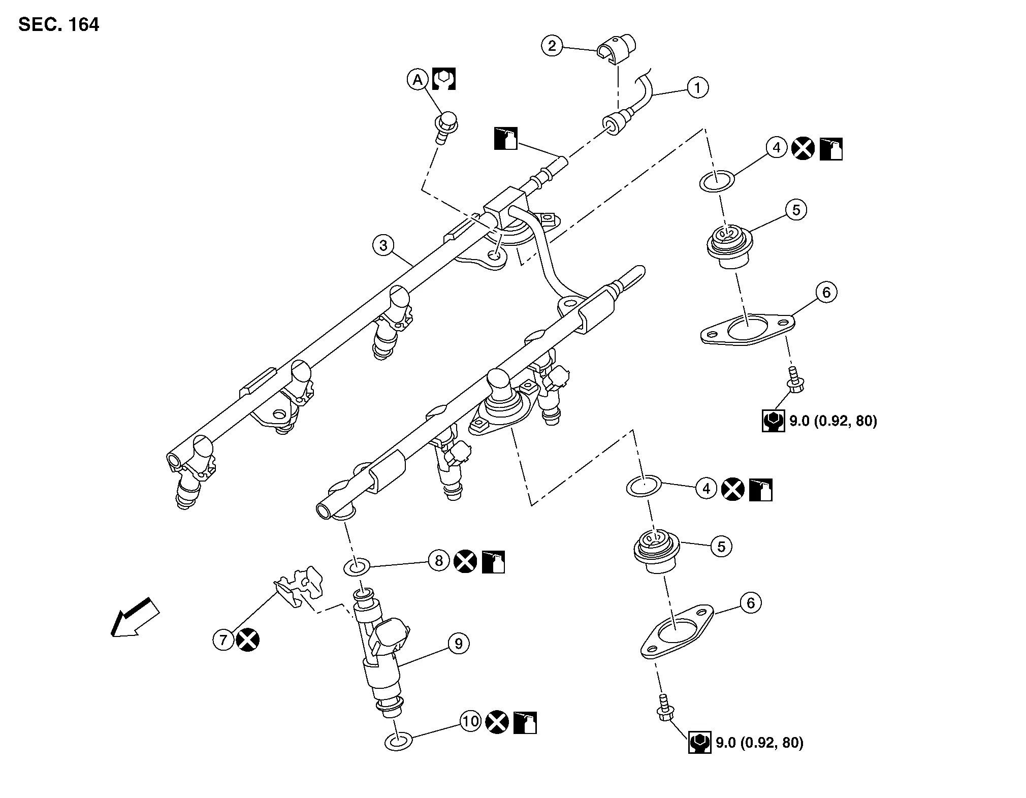
| 1. | Fuel feed hose | 2. | Quick connector cap | 3. | Fuel tube |
| 4. | O-ring | 5. | Fuel damper | 6. | Fuel damper cap |
| 7. | Clip | 8. | O-ring (black) | 9. | Fuel injector |
| 10. | O-ring (green) | A. | Refer to Removal and Installation. | Engine front |
REMOVAL
WARNING:
-
Put a “CAUTION: FLAMMABLE” sign in the workshop.
-
Be sure to work in a well ventilated area and furnish workshop with a CO2 fire extinguisher.
-
Do not smoke while servicing fuel system. Keep open flames and sparks away from the work area.
-
Do not drain engine coolant when engine is hot to avoid the danger of being scalded.
CAUTION:
-
Apply new engine oil when installing the parts as specified to do so.
-
Do not remove or disassemble parts unless instructed.
 NOTE:
NOTE:
When removing components such as hoses, tubes/lines, etc., cap or plug openings to prevent fluid from spilling.
Remove engine room cover. Refer to Removal and Installation.
Release the fuel pressure. Refer to Work Procedure.
Disconnect the battery negative terminal. Refer to Removal and Installation.
Remove intake manifold collector. Refer to Removal and Installation.
When separating fuel feed hose and fuel tube connection, disconnect quick connector using Tool as follows:
| Tool number | : 16441 6N210 (J-45488) |
CAUTION:
Disconnect quick connector by using the special service tool, not by prying out retainer tabs.
-
With the sleeve side of Tool facing toward the quick connector, install the Tool onto fuel tube.
-
Insert the Tool (A) into quick connector (2) until sleeve (B) contacts and goes no further. Hold Tool in that position.
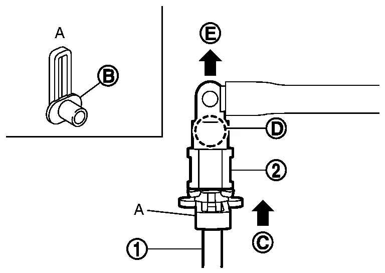
(C) : Insert and retain CAUTION:
Inserting Tool with excess force will not disconnect quick connector. Hold quick connector release where it contacts and goes no further.
-
Draw and pull out quick connector straight from fuel tube (1).
CAUTION:
-
Pull quick connector (E) holding position (D) as shown.
-
Do not pull with lateral force applied. O-ring inside quick connector may be damaged.
-
Prepare container and cloth beforehand as fuel will leak out.
-
Avoid fire and sparks.
-
Keep parts away from heat source. Be especially careful when welding is performed around them.
-
Do not expose parts to battery electrolyte or other acids.
-
Do not bend or twist connection between quick connector and fuel feed hose (with damper) during installation/removal.
-
To keep the connecting portion clean and to avoid damage and foreign materials, cover them completely with plastic bags (A) or something similar.
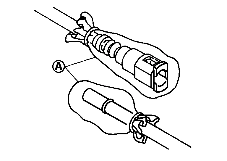
-
Disconnect harness connector from fuel injector.
Loosen bolts in reverse order as shown, and remove fuel tube and fuel injector assembly.
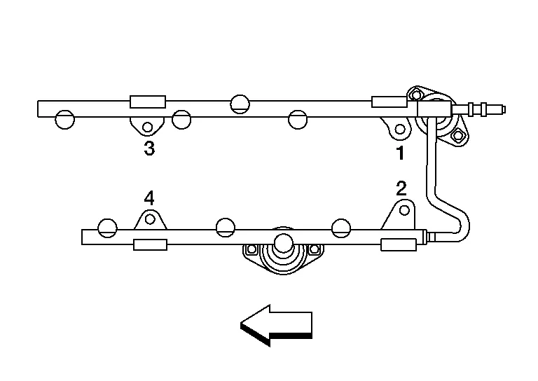
| : Engine front |
CAUTION:
Do not tilt fuel tube or remaining fuel in pipes may flow out from pipes.
Remove fuel injector from fuel tube as follows:Open and remove clip (1).
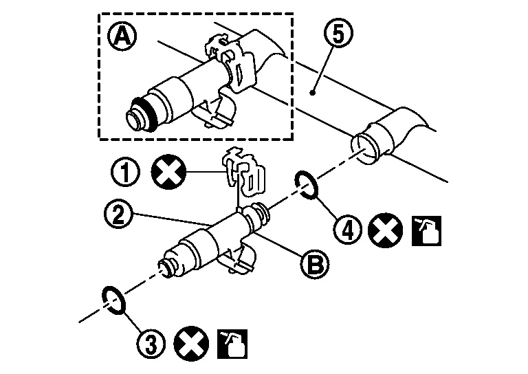
| (3) | : O-ring (green) |
| (4) | : O-ring (black) |
| (A) | : Installed condition |
| (B) | : Clip mounting groove |
CAUTION:
-
Be careful or the remaining fuel in the fuel tube may spill.
-
Be careful not to damage injector nozzle during removal.
-
Do not bump or drop fuel injector.
-
Do not disassemble fuel injector.
-
Do not reuse O-rings.
Remove fuel damper from fuel tube.
INSTALLATION
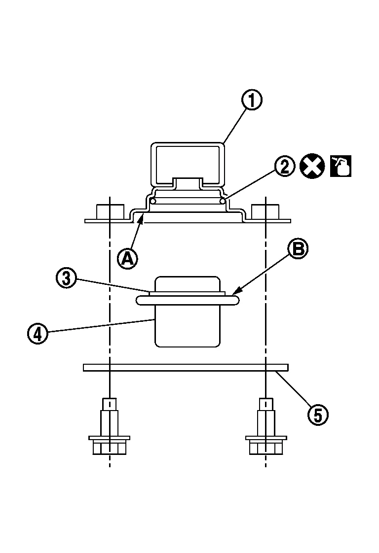
Install fuel damper as follows:Install new O-ring (2) to fuel tube (1) as shown. When handling new O-ring, be careful of the following caution:
CAUTION:
-
Do not reuse O-rings.
-
Handle O-ring with bare hands. Do not wear gloves.
-
Lubricate O-ring with new engine oil.
-
Do not clean O-ring with solvent.
-
Check that O-ring and its mating part are free of foreign material.
-
When installing O-ring, be careful not to scratch, nick or damage it. Also be careful not to twist or stretch O-ring.
-
Insert new O-ring straight into fuel tube. Be sure O-ring is centered and not twisted.
CAUTION:
-
Insert fuel damper until (B) is touching (A) of fuel tube.
-
Insert straight, checking that the axis is lined up.
-
Do not pressure-fit with excessive force.
Reference value : 130 N (13.3 kg, 29.2 lb)
-
After tightening bolts, check that there is no gap between fuel damper cap (5) and fuel tube.
Install new O-rings to fuel injector paying attention to the following.
CAUTION:
-
Do not reuse O-rings.
-
Upper and lower O-ring are different. Be careful to install them in the correct location.
-
Handle O-ring with bare hands. Do not wear gloves.
-
Lubricate O-ring with new engine oil.
-
Do not clean O-ring with solvent.
-
Check that O-ring and its mating part are free of foreign material.
-
When installing O-ring, be careful not to scratch or nick it. Also be careful not to twist or stretch O-ring.
-
Insert O-ring straight into fuel injector. Be sure that the O-ring is centered and not twisted.
Install fuel injector to fuel tube as follows:Insert clip (3) into clip groove (F) on fuel injector (5).
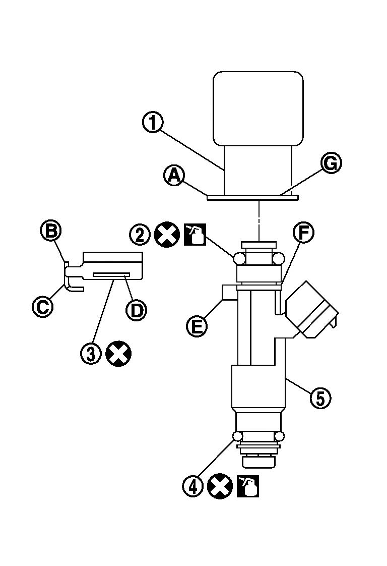
| (2) | : O-ring (black) |
| (4) | : O-ring (green) |
-
Insert clip so that protrusion (E) of fuel injector matches cutout (C) of clip.
CAUTION:
-
Do not reuse clip. Replace it with new one.
-
Be careful to keep clip from interfering with O-ring. If interference occurs, replace O-ring.
-
Do not reuse O-rings.
-
-
Insert it while matching it to the axial center.
-
Insert fuel injector so that protrusion (A) of fuel tube matches cutout (B) of clip.
-
Check that fuel tube flange (G) is securely fixed in flange groove (D) on clip.
CAUTION:
Do not pressure-fit with excessive force.
| Reference value | : 147 N (15.0 kg, 33.0 lb) |
-
Check that protrusions of fuel injectors and fuel tubes are aligned with cutouts of clips after installation.
Install fuel tube and fuel injector assembly to intake manifold.
CAUTION:
Be careful not to let tip of injector nozzle come in contact with other parts.
-
Tighten bolts in two steps in numerical order as shown.

: Engine front 1st step : 10.1 N·m (1.0 kg-m, 7 ft-lb) 2nd step : 22.0 N·m (2.2 kg-m, 16 ft-lb)
Connect fuel injector harness.
Install intake manifold collector. Refer to Removal and Installation.
Connect quick connector between fuel feed hose and fuel tube connection with the following procedure:Check no foreign substances are on the fuel tube or quick connector and that they are not damaged. Apply a light coating of new engine oil around fuel tube from tip end to spool end. Align center to insert quick connector straightly into fuel tube.
-
Insert quick connector (1) to fuel tube until top spool (2) is completely inside quick connector, and 2nd level spool (3) exposes right below quick connector.
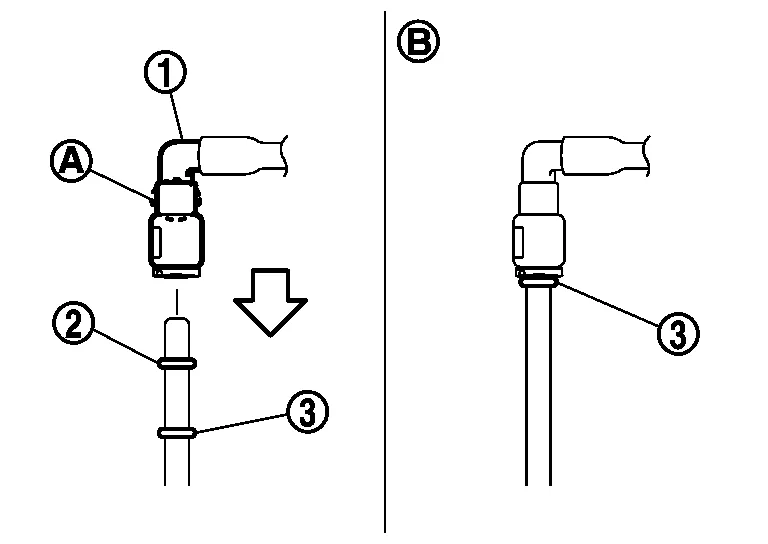
(B) : Installed condition : Upright insertion
CAUTION:
-
Hold (A) position as shown when inserting fuel tube into quick connector.
-
Carefully align center to avoid inclined insertion to prevent damage to O-ring inside quick connector.
-
Insert until you hear a “click” sound and actually feel the engagement.
-
To avoid misidentification of engagement with a similar sound, be sure to perform the next step.
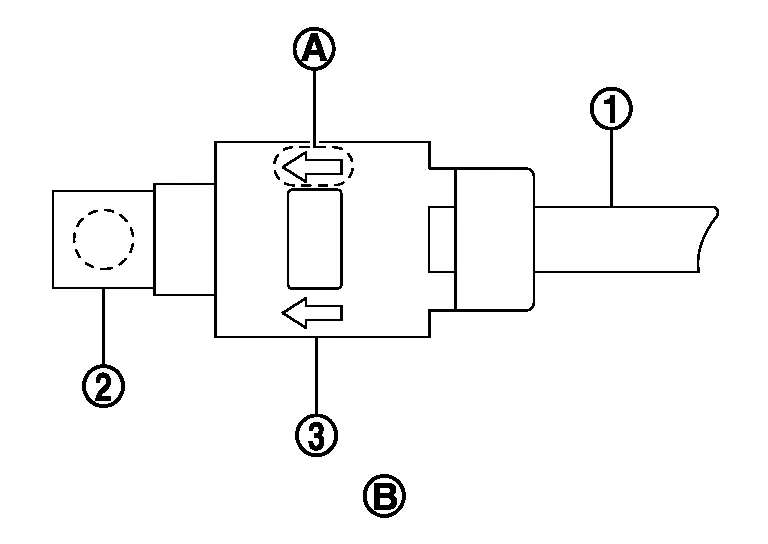
| (1) | : Fuel feed hose |
| (2) | : Fuel tube |
| (B) | : Upper view |
-
Install quick connector cap with arrow (A) on surface facing in direction of quick connector (fuel feed hose side).
CAUTION:
If quick connector cap cannot be installed smoothly, quick connector may have not been installed correctly. Check connection again.
Secure fuel feed hose to clamp of quick connector cap.Installation of the remaining components is in the reverse order of removal.
INSPECTION AFTER INSTALLATION
Check For Fuel Leaks
Turn ignition switch ON with the engine stopped. With fuel pressure applied to fuel piping, check for fuel leaks at connection points. Repair as necessary.
NOTE:
Use mirrors for checking at points out of clear sight.
Start the engine. With engine speed increased, check again for fuel leaks at connection points. Repair as necessary.
WARNING:
Do not touch the engine immediately after stopped, as the engine becomes extremely hot.
NOTE:
Use mirrors for checking on connections out of the direct line of sight.
-
Perform procedures for “Throttle Valve Closed Position Learning” after finishing repairs. Refer to Description.
-
If electric throttle control actuator is replaced, perform procedures for “Idle Air Volume Learning” after finishing repairs. Refer to Description.
 Rocker Cover
Exploded View
1.
Camshaft position sensor (Bank 2)
2.
O-rings
3.
Camshaft position sensor (Bank 1)
4.
O-rings
5.
Rocker cover (Bank 1)
6...
 Valve Timing Control
Exploded View
1.
Front timing chain case
2.
Valve timing control cover gasket (bank 1)
3.
O-ring
4.
O-ring
5.
Intake valve timing intermediate lock control solenoid valve (bank 1)
6...
Other information:
Nissan Murano (Z52) 2015-2024 Service Manual: Sensor Power Supply2 Circuit
Diagnosis Procedure ECM supplies a voltage of 5 V to some of the sensors systematically divided into 2 groups, respectively. Accordingly, when a short circuit develops in a sensor power source, a malfunction may occur simultaneously in the sensors belonging to the same group as the short-circuited sensor...
Nissan Murano (Z52) 2015-2024 Owners Manual: Shift lock release
If the battery charge is low or discharged, the shift lever may not be moved from the P (Park) position even with the brake pedal depressed and the shift lever button pressed. To move the shift lever, perform the following procedure: Place the ignition switch in the OFF or LOCK position...
Categories
- Manuals Home
- Nissan Murano Owners Manual
- Nissan Murano Service Manual
- Tire rotation
- All-Wheel Drive (AWD) (if so equipped)
- Shift lock release
- New on site
- Most important about car
Unfastening the seat belts. Checking seat belt operation
Unfastening the seat belts

To unfasten the seat belt, press the button
on the buckle  . The seat belt
automatically
retracts.
. The seat belt
automatically
retracts.