Nissan Murano: Driveline :: Rear Propeller Shaft: C-Cvj-C / Removal and Installation. Rear Propeller Shaft
 |
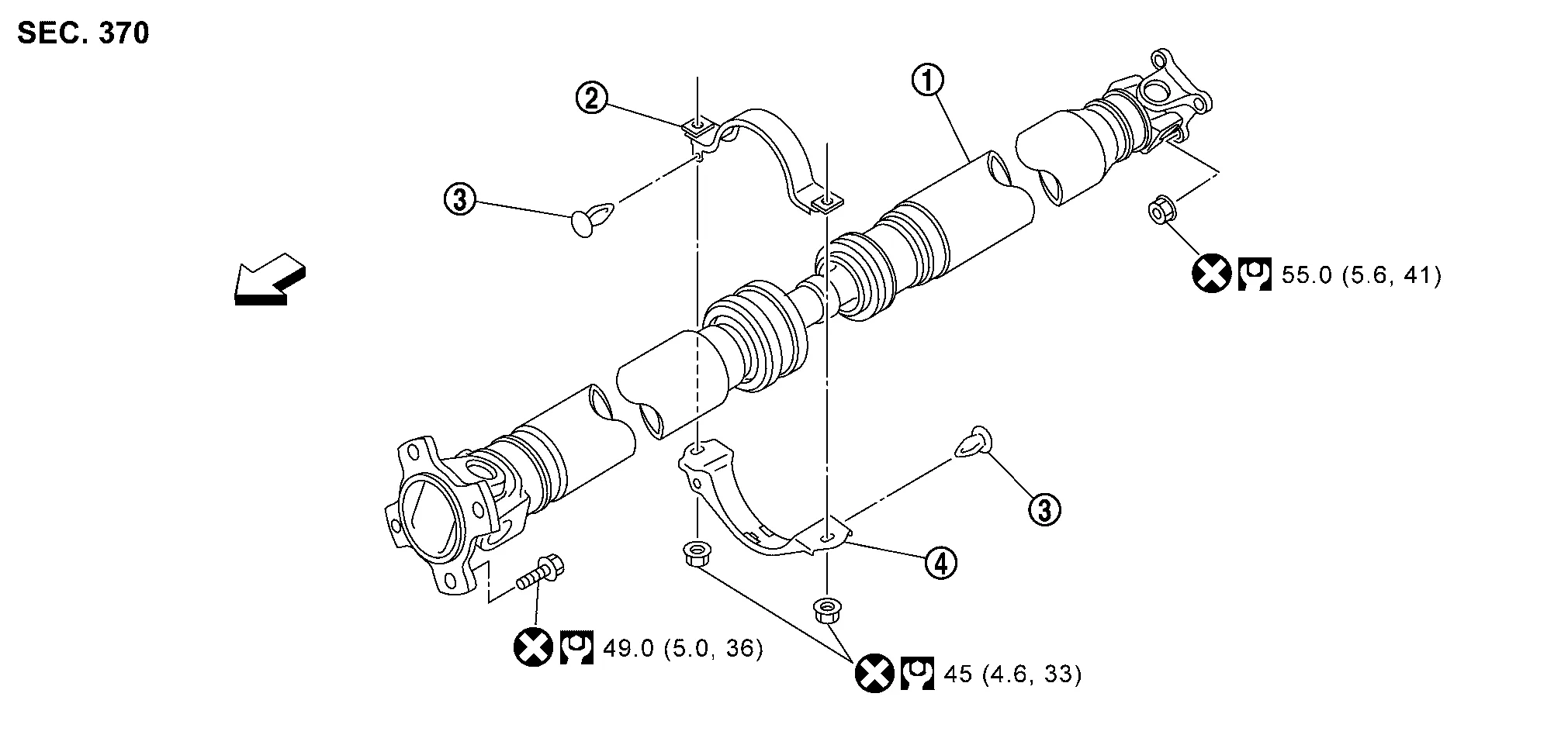
Propeller shaft assembly |  |
Center bearing mounting bracket (upper) |  |
Clip |
 |
Center bearing mounting bracket (lower) | ||||
 : N·m (kg-m, ft-lb) : N·m (kg-m, ft-lb) |
|||||
 : Always replace after every disassembly. : Always replace after every disassembly. |
|||||
REMOVAL
Shift transaxle to the neutral position and then release parking brake.
Remove front exhaust tube. Refer to Exploded View.
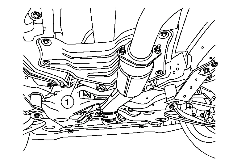
Remove heat insulator (1).
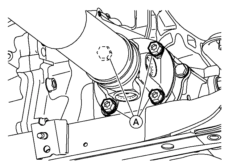
Put matching marks (A) on propeller shaft flange yoke and transfer companion flange.
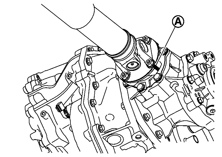
CAUTION:
For matching mark, use paint. Do not damage propeller shaft flange yoke and transfer companion flange.
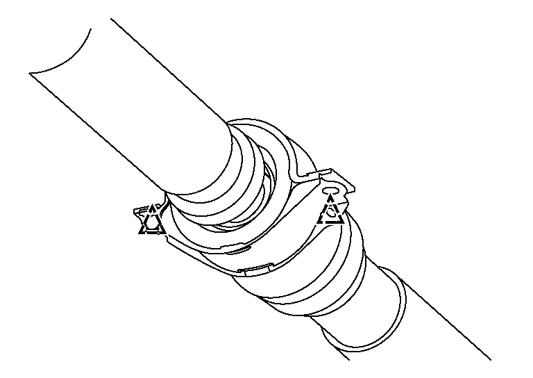
Put matching marks (A) on propeller shaft flange yoke and electric controlled coupling.
CAUTION:
-
For matching mark, use paint. Do not damage propeller shaft flange yoke and electric controlled coupling.
-
If the tip of stud bolt of electric controlled coupling has a paint mark, place a matching mark for identification of the position of applicable stud bolt.
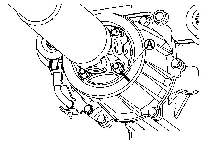
Loosen mounting nuts (A) of center bearing mounting bracket.
 NOTE:
NOTE:
Tighten mounting nuts (A) temporarily to prevent drop of propeller shaft.
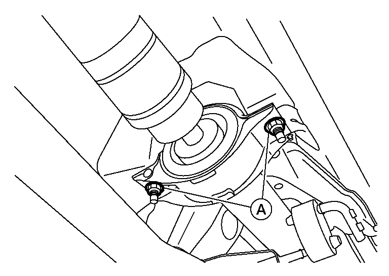
Remove propeller shaft assembly fixing bolts (A), and separate propeller shaft assembly from transfer companion flange.
Remove propeller shaft assembly fixing nuts (A), and separate propeller shaft assembly from electric controlled coupling (1) of final drive.

Remove center bearing mounting bracket mounting nuts.
Remove propeller shaft assembly.
Remove clips and then remove center bearing mounting bracket (upper/lower).
 |
Clip |
Perform inspection after removal. Refer to Inspection.
INSTALLATION
Note the following, and install in the reverse order of removal.
CAUTION:
Do not reuse propeller shaft nuts and bolts.
-
After removing propeller shaft, replace stud bolts on electric controlled coupling. Refer to Removal and Installation.
-
Remove any moisture, oil, or foreign material from matching surface on transfer companion flange, electric controlled coupling and propeller shaft flange.
-
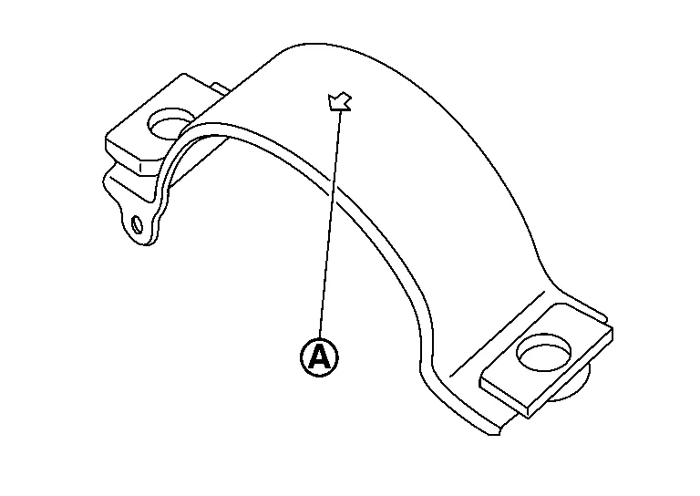
Install center bearing mounting bracket (upper) with its arrow mark (A) facing forward.
-
Adjust position of center bearing mounting bracket (upper) (1), center bearing mounting bracket (lower) (2) sliding back and forth to prevent play in thrust direction of center bearing insulator (3). Install center bearing mounting bracket (upper/lower) to Nissan Murano vehicle.

-
Center bearing mounting bracket fixing nuts must be tightened in the order from left to right.
-
Align matching marks (A) to install propeller shaft flange yoke and electric controlled coupling of final drive.
-
Align matching marks (A) to install propeller shaft flange yoke and transfer companion flange.
-
If propeller shaft assembly, final drive assembly or electric controlled coupling has been replaced, connect propeller shaft assembly and electric controlled coupling of final drive as follows:
-
Install propeller shaft (1) while aligning its matching mark (A) of propeller shaft with matching mark (B) on stud bolt of electric controlled coupling (2) as close as possible.
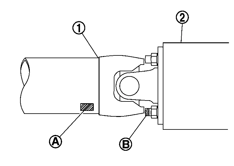
CAUTION:
When replacing stud bolt, use the painted matching mark in removal as a guide.
-
-
Perform inspection after installation. Refer to Inspection.
INSPECTION AFTER REMOVAL
Appearance
Check propeller shaft tube surface for dents or cracks.
If malfunction is detected, replace propeller shaft assembly.
Propeller Shaft Runout
Check propeller shaft runout at measuring points with a dial indicator. If runout exceeds specifications, replace propeller shaft assembly.
| Propeller shaft runout | : Refer to Propeller Shaft Runout. |
-
Propeller shaft runout measuring point (Point “
 ”).
”).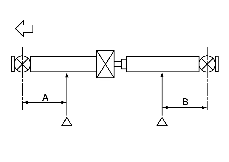

: Front side Dimension A : 568 mm (22.36 in) B : 516 mm (20.31 in)
Center Bearing
Check center bearing for noise and damage. If malfunction is detected, replace propeller shaft assembly.
CAUTION:
Do not disassemble center bearing.
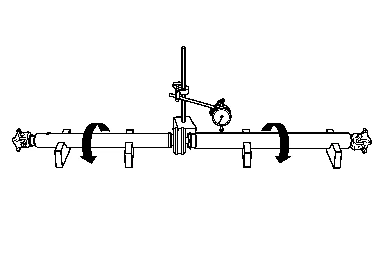
Journal Axial Play
As shown in the figure, while fixing yoke on one side, check axial play of joint. If it is outside the standard, replace propeller shaft assembly.

| Journal axial play | : Refer to Journal Axial Play. |
CAUTION:
Do not disassemble joints.
INSPECTION AFTER INSTALLATION
After assembly, perform a driving test to check propeller shaft vibration. If vibration occurred, separate propeller shaft from final drive. Reinstall propeller shaft by changing the phase between electric controlled coupling stud bolt and propeller shaft by the one bolt hole at a time. Then perform driving test and check propeller shaft vibration again at each point.
 Periodic Maintenance. Rear Propeller Shaft
Inspection
LOOSENESS OF CONNECTED PARTCheck each fixing bolt and nut for looseness using torque wrench. For each tightening torque, refer to Exploded View...
 Service Data and Specifications (sds). Service Data and Specifications (sds)
General Specifications
Applied model Axle AWD
Engine VQ35DE
Transaxle CVT
Propeller shaft model C-CVJ-C
Number of joints
3
Joint type
1st joint
Universal (Shell type)
2nd joint
CVJ type
3rd joint
Universal (Shell type)
Coupling method
Transfer side
Flange type
Rear final drive side
Flange type
Shaft length
1st (Spider to CVJ joint center)
1265 mm (49...
Other information:
Nissan Murano (Z52) 2015-2024 Service Manual: Exit Assist Function
System Description SYSTEM DIAGRAMSIGNAL TRANSMISSION FUNCTION LISTSeveral types of signals are transmitted from the following units to the driver seat control unit via CAN communication. Component Signal BCM Ignition switch signal Door switch signal TCM Shift position signal IPDM E/R Detention switch signal DESCRIPTIONWhen exiting, if the conditions are satisfied, the seat is moved backward from normal sitting position and the steering column is moved up...
Nissan Murano (Z52) 2015-2024 Service Manual: Transmission Range Switch
Exploded View 1. Lock washer 2. Manual lever 3. Transmission range switch 4. CVT 5. Manual shaft Removal and Installation REMOVALRemove air cleaner and air duct. Refer to Removal and Installation. Remove control cable nut (A)...
Categories
- Manuals Home
- Nissan Murano Owners Manual
- Nissan Murano Service Manual
- Jacking up vehicle and removing the damaged tire
- How to enable/disable the LDW system
- Memory storage function (key-link)
- New on site
- Most important about car
Autolight system
The autolight system allows the headlights to turn on and off automatically. The autolight system can:
Turn on the headlights, front parking, tail, license plate and instrument panel lights automatically when it is dark. Turn off all the lights (except daylight running lights) when it is light. Keep all the lights on for a period of time after you place the ignition switch in the OFF position and all doors are closed.