Nissan Murano: Engine Mechanical :: Removal and Installation / Oil Pan and Oil Strainer
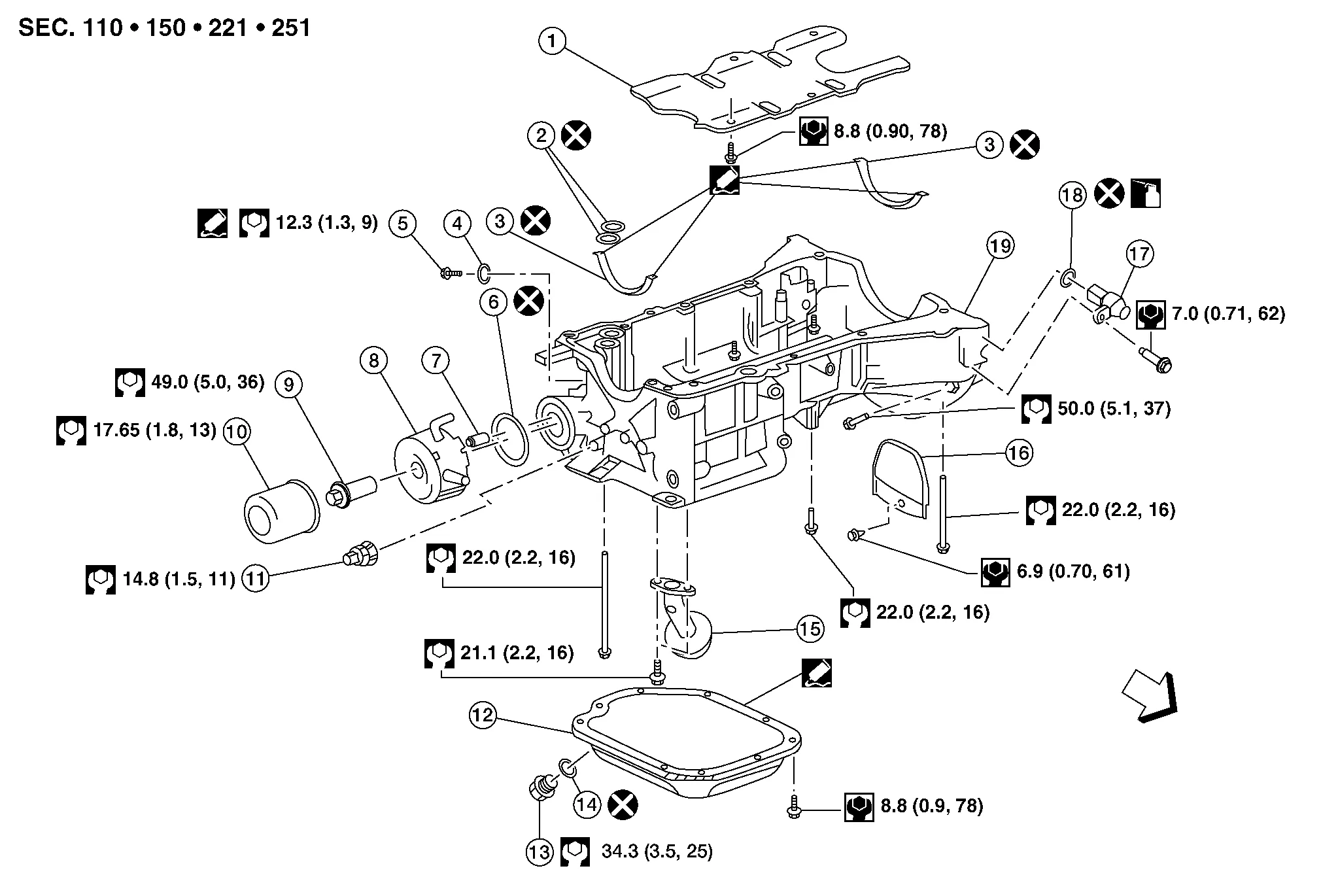
| 1. | Oil pan baffle | 2. | O-ring | 3. | Upper oil pan gasket |
| 4. | Blind plug O-ring | 5. | Blind plug | 6. | Oil cooler O-ring |
| 7. | Relief valve | 8. | Oil cooler | 9. | Oil cooler connector |
| 10. | Oil filter | 11. | Oil pressure sensor | 12. | Lower oil pan |
| 13. | Drain plug | 14. | Drain plug washer | 15. | Oil strainer |
| 16. | Rear cover plate | 17. | Crankshaft position sensor (POS) | 18. | O-ring |
| 19. | Upper oil pan | Front |
REMOVAL
WARNING:
You should not remove the oil pan until the exhaust system and cooling system have completely cooled off.
Drain the engine oil. Refer to Changing Engine Oil.
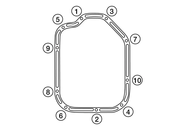
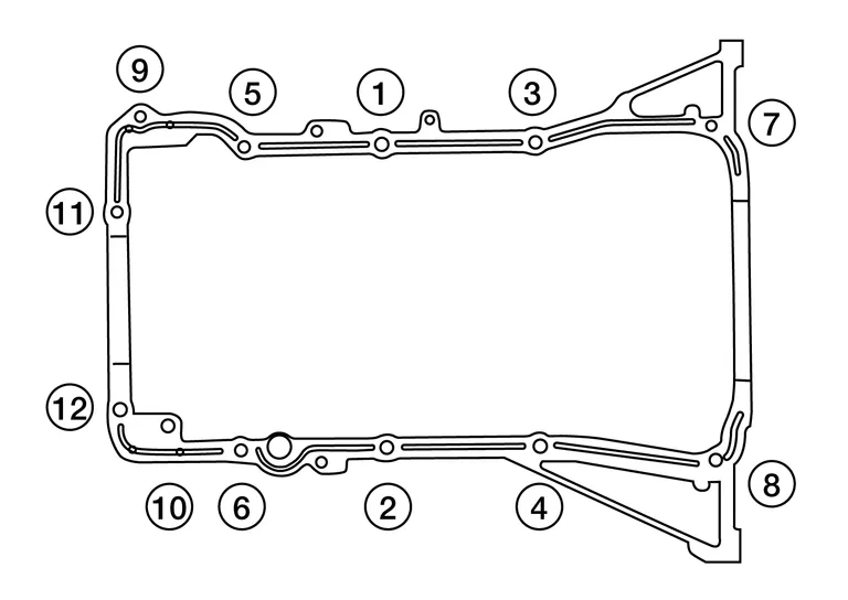
Loosen the lower oil pan bolts in reverse order as shown.
Remove the lower oil pan.
CAUTION:
Do not damage the mating surfaces.
-
After removing the bolts, separate the mating surface and remove the old liquid gasket using Tool (A).
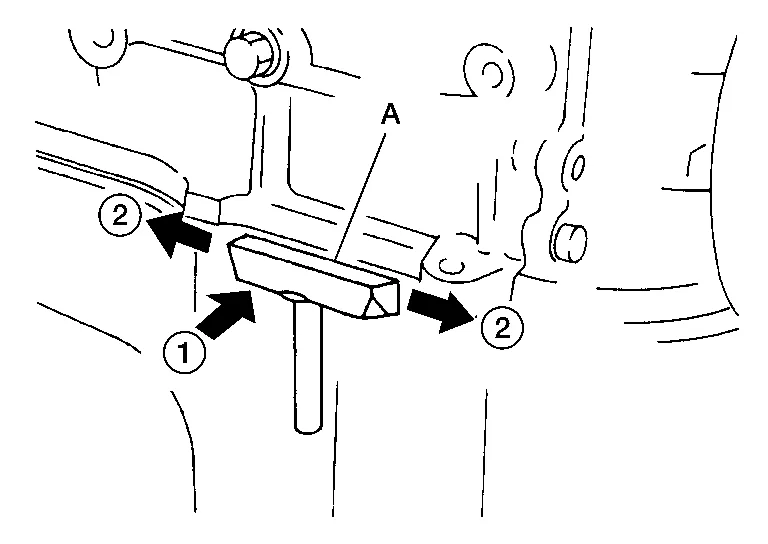
Tool number (A) : KV10111100 (J-37228) -
In areas where the Tool is difficult to use, use a plastic hammer to lightly tap (1) the Tool where the liquid gasket is applied. Use a plastic hammer to slide (2) the Tool by tapping on the side.
Remove the old sealant from the bolt holes and threads.
INSPECTION AFTER REMOVAL
Clean debris from the oil strainer.
INSTALLATION
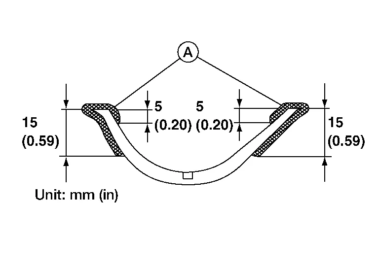
Apply a continuous bead of sealant to the lower oil pan.
-
Use Genuine Silicone RTV Sealant, or equivalent. Refer to Recommended Chemical Products and Sealants.
-
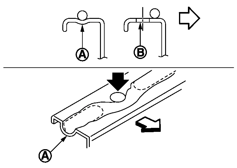
Be sure the sealant is 4.5 - 5.5 mm (0.177 - 0.217 in) wide.
CAUTION:
-
Installation should be done within 5 minutes after applying liquid gasket.
-
Do not fill the engine with engine oil for at least 30 minutes after the components are installed to allow the sealant to cure.
-
| (A) | : Groove |
| (B) | : Bolt hole |
| : Inside |
Install the lower oil pan. Tighten the lower oil pan bolts in order as shown.
CAUTION:
-
Installation should be done within 5 minutes after applying liquid gasket.
-
Do not fill the engine with engine oil for at least 30 minutes after the components are installed to allow the sealant to cure.
Refill the engine with oil. Refer to Changing Engine Oil.
INSPECTION AFTER INSTALLATION
Inspect the engine oil level. Refer to Inspection.
Start the engine and check for leaks. Refer to Inspection. Repair as necessary.
REMOVAL
WARNING:
-
Do not remove the oil pan until the exhaust system and cooling system have completely cooled off.
-
When removing the front and rear engine through bolts and nuts, lift the engine up slightly for safety.
CAUTION:
When removing the upper oil pan from the engine, first remove the crankshaft position sensor (POS).
Be careful not to damage sensor edges or signal plate teeth.
 NOTE:
NOTE:
When removing components such as hoses, tubes/lines, etc., cap or plug openings to prevent fluid from spilling.
Remove the engine from the vehicle. Refer to Removal and Installation (FWD) or Removal and Installation (AWD).
Install the engine on engine stand (A). Any commercially available engine stand (A) can be used.
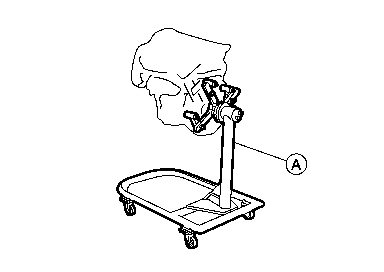
CAUTION:
-
Use an engine stand (A) that has a load capacity [approximately 240kg (529 lb) or more] large enough for supporting the engine weight.
-
Before removing the hanging chains, make sure the engine stand (A) is stable and there is no risk of overturning.
Remove the oil dipstick.
Remove the drive belt. Refer to Removal and Installation.
Disconnect the harness connector from A/C compressor.
Remove the A/C compressor bolts and remove the A/C compressor. Refer to Removal and Installation.
Remove water pipe bolts.
Disconnect the water hoses from the engine oil cooler.
Remove the oil filter and engine oil cooler from the upper oil pan. Refer to Removal and Installation (Upper Oil Pan).
Remove the oil pressure switch, and the crankshaft position sensor (POS) from the upper oil pan.
Remove the lower oil pan. Refer to Removal and Installation (Lower Oil Pan).
Remove the oil strainer.
Remove the upper oil pan.

Remove rear engine mount buffer bracket.
Remove the O-rings (2) from the bottom of the cylinder block (1) and oil pump housing. Use new O-rings for installation.

| : Engine front |
CAUTION:
Do not reuse O-rings.
Remove front cover gasket (A) and rear oil seal retainer gasket (B).
| : Engine front |
If reinstalling the original oil pan, remove the old sealant from the mating surfaces using a suitable tool (A).
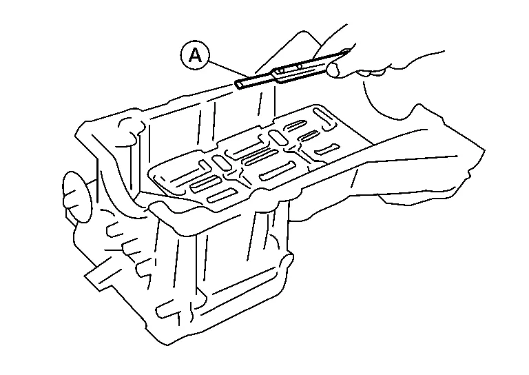
-
Also remove the old sealant from mating surface of the cylinder block.
-
Remove the old sealant from the bolt holes and threads.
CAUTION:
Do not scratch or damage the mating surfaces when cleaning off the old sealant.
INSPECTION AFTER REMOVAL
Clean debris from oil strainer.
INSTALLATION
Install oil strainer and tighten bolt to specified torque.
| Oil strainer bolts | : 21.1 N·m (2.2 kg-m, 16 ft-lb) |
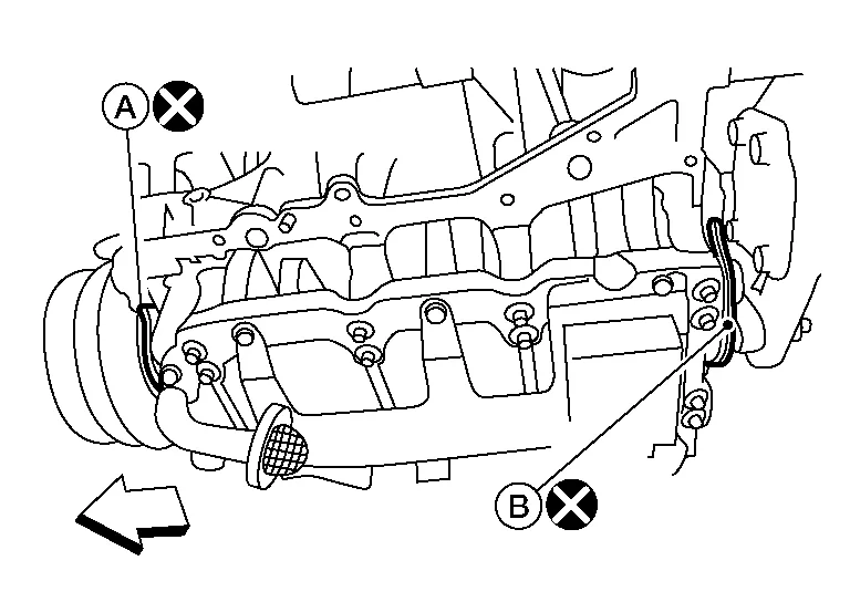
Apply Genuine Silicone RTV Sealant or equivalent (A) to the front cover gasket and the rear oil seal retainer gasket as shown. Refer to Recommended Chemical Products and Sealants.
CAUTION:
-
Installation should be done within 5 minutes after applying liquid gasket.
-
Do not fill the engine with oil for at least 30 minutes after the components are installed to allow the sealant to cure.
Install the front cover gasket (A) and rear oil seal retainer gasket (B) as shown.
CAUTION:
Do not reuse front cover gasket or rear oil seal retainer gasket.
| : Engine front |
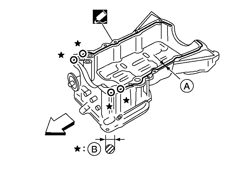
Apply a bead of sealant to the cylinder block mating surface of the upper oil pan as shown.
CAUTION:
-
Installation should be done within 5 minutes after applying liquid gasket.
-
Do not fill the engine with oil for at least 30 minutes after the components are installed to allow the sealant to cure.
NOTE:
-
Apply liquid gasket to the outside of bolt holes 5, 6, 10, 11 and 12.
-
Apply liquid gasket to the inside of the other bolt holes.
| : Engine front |
| (A) | : Groove |
| (B) | : Bolt hole |
| : Inside |
Install new O-rings (2) on the cylinder block (1) and oil pump body.
CAUTION:
Do not reuse O-rings.
| : Engine front |
Install the upper oil pan.
-
Tighten bolts (1) and (2) to specification within 5 minutes of applying the liquid gasket.
-
Tighten the remaining upper oil pan bolts to specification in the order shown.
CAUTION:
-
Installation should be done within 5 minutes after applying liquid gasket.
-
Do not fill the engine with oil for at least 30 minutes after the components are installed to allow the sealant to cure.
Install the lower oil pan. Refer to Removal and Installation (Lower Oil Pan).
Installation of the remaining components is in the reverse order of removal.
CAUTION:
-
Do not allow crankshaft position sensor (POS) to contact magnet.
-
Do not allow foreign material to contact tip of crankshaft position sensor (POS).
-
Do not allow foreign material to contact crankshaft position sensor (POS) O-ring.
-
Do not use a crankshaft position sensor (POS) that has been dropped.
-
Do not use an oil pressure sensor that has been dropped.
INSPECTION AFTER INSTALLATION
-
Before starting engine, check oil/fluid levels including engine coolant and engine oil. If there is less than required quantity, fill to the specified level. Refer to Fluids and Lubricants.
-
Use procedure below to check for fuel leakage.
-
Turn ignition switch ON (with engine stopped). With fuel pressure applied to fuel piping, check for fuel leakage at connection points.
-
Start engine. With engine speed increased, check again for fuel leakage at connection points.
-
Run engine to check for unusual noise and vibration.
NOTE:
If hydraulic pressure inside timing chain tensioner drops after removal and installation, slack in the guide may generate a pounding noise during and just after engine start. However, this is normal. Noise will stop after hydraulic pressure rises.
-
Warm up engine thoroughly to make sure there is no leakage of fuel, exhaust gas, or any oils/fluids including engine oil and engine coolant.
-
Bleed air from passages in lines and hoses, such as in cooling system.
-
After cooling down engine, again check oil/fluid levels including engine oil and engine coolant. Refill to specified level, if necessary.
-
Summary of the inspection items:
Item Before starting engine Engine running After engine stopped Engine coolant Level Leakage Level Engine oil Level Leakage Level Transmission/transaxle fluid A/T and CVT Models Leakage Level/Leakage Leakage M/T Models Level/Leakage Leakage Level/Leakage Other oils and fluids* Level Leakage Level Fuel Leakage Leakage Leakage Exhaust gas — Leakage — *Power steering fluid, brake fluid, etc.
 Exhaust Manifold and Three Way Catalyst
Exploded View
1.
Gasket
2.
Exhaust manifold (bank 1)
3.
Exhaust manifold cover (bank 1)
4.
Air fuel ratio sensor 1 (bank 1)
5.
Ring gasket
6...
 Ignition Coil
Exploded View
1.
Ignition coil
2.
Spark plug
3.
Rocker cover (Bank 1)
4.
Rocker cover (Bank 2)
Front
Removal and Installation (bank 2)
REMOVALRemove engine room cover...
Other information:
Nissan Murano (Z52) 2015-2024 Service Manual: Auto Anti-Dazzling Inside Mirror Does Not Operate
Diagnosis Procedure CHECK AUTO-ANTI DAZZLING INSIDE MIRROR SYSTEM Check auto anti-dazzling inside mirror system. Is the inspection result normal? YES>> GO TO 2. NO>> Repair or replace the malfunctioning parts. REPLACE GLASS MIRROR Replace glass mirror...
Nissan Murano (Z52) 2015-2024 Service Manual: C1110 Abs Actuator and Electric Unit (control Unit)
DTC Description DTC DETECTION LOGIC DTC No. CONSULT screen item (Trouble diagnosis content) DTC detected condition C1110 CONTROLLER FAILURE (Controller failure) Diagnosis condition When ignition switch ON. Signal (terminal) — Threshold When there is an internal malfunction in the ABS actuator and electric unit (control unit)...
Categories
- Manuals Home
- Nissan Murano Owners Manual
- Nissan Murano Service Manual
- Rear bench seat adjustment
- Checking engine oil level
- All-Wheel Drive (AWD) (if so equipped)
- New on site
- Most important about car
LATCH (Lower Anchors and Tethers for CHildren) system

LATCH system lower anchor locations - bench seat
Your vehicle is equipped with special anchor points that are used with LATCH system compatible child restraints. This system may also be referred to as the ISOFIX or ISOFIX compatible system. With this system, you do not have to use a vehicle seat belt to secure the child restraint unless the combined weight of the child and child restraint exceeds 65 lbs. (29.5 kg). If the combined weight of the child and child restraint is greater than 65 lbs. (29.5 kg), use the vehicle’s seat belt (not the lower anchors) to install the child restraint. Be sure to follow the child restraint manufacturer’s instructions for installation.