Nissan Murano: Engine Mechanical :: Removal and Installation / Exhaust Manifold and Three Way Catalyst

| 1. | Gasket | 2. | Exhaust manifold (bank 1) | 3. | Exhaust manifold cover (bank 1) |
| 4. | Air fuel ratio sensor 1 (bank 1) | 5. | Ring gasket | 6. | Three way catalyst (bank 1) |
| 7. | Three way catalyst support (bank 1) | 8. | Heated oxygen sensor 2 (bank 1) | 9. | Three way catalyst (bank 2) |
| 10. | Three way catalyst support (bank 2) | 11. | Heated oxygen sensor 2 (bank 2) | 12. | Ring gasket |
| 13. | Exhaust manifold (bank 2) | 14. | Exhaust manifold cover (bank 2) | 15. | Air fuel ratio sensor 1 (bank 2) |
| A. | To oil pan (upper). Refer to Exploded View. | B. | Upper mark | Engine front |
REMOVAL
WARNING:
-
Perform the work when the exhaust system has completely cooled down.
-
When removing the front and rear engine mounting through bolts and nuts, lift the engine up slightly for safety.
 NOTE:
NOTE:
When removing components such as hoses, tubes/lines, etc., cap or plug openings to prevent fluid from spilling.
Remove the air cleaner case (upper), air cleaner case (lower), and air duct hose and resonator assembly. Refer to Removal and Installation.
Remove the battery and battery tray assembly. Refer to Removal and Installation.
Remove the front wheels and tires using power tool. Refer to Removal and Installation.
Remove the front under cover. Refer to Removal and Installation.
Remove the fender protector side covers (LH and RH). Refer to Exploded View.
Remove the radiator assembly. Refer to Removal and Installation.
Remove the engine cooling fan shroud and motor assembly. Refer to Removal and Installation.
Remove the front exhaust tube. Refer to Exploded View.
Support the engine with a suitable tool.
Remove the engine mount bracket (front). Refer to Exploded View (FWD) or Exploded View (AWD).
Remove the three way catalyst support (bank 2).
Remove heated oxygen sensor 2 (bank 2), air fuel ratio (A/F) sensor 1 (bank 2).Disconnect harness connector from each sensor, and remove the harness from the bracket and middle clamp. Remove both heated oxygen sensor and air fuel ratio (A/F) sensor using Tool.
| Tool numbers | : KV10114400 (J-38365) |
| : KV991J0050 (J-44626) |
CAUTION:
-
Be careful not to damage heated oxygen sensors or air fuel ratio (A/F) sensors.
-
Discard any heated oxygen sensor which has been dropped from a height of more than 0.5 m (19.7 in) onto a hard surface such as a concrete floor; replace with a new sensor.
Remove exhaust manifold and three way catalyst heat shields with power tool.
Remove the three way catalyst (bank 2) by loosening the bolts first and then removing the nuts and through bolts.
Loosen and remove the exhaust manifold nuts in the reverse order as shown.

| : Engine front |
NOTE:
Number 7 and 8 are not applicable to removal.
Remove the exhaust manifold (bank 2) and gasket.
INSPECTION AFTER REMOVAL
Surface Distortion
-
Use suitable tools (A/B) to check the flatness of the exhaust manifold mating surfaces.

Limit : 0.3 mm (0.012 in) -
Replace the exhaust manifold if the measurement exceeds specifications.
INSTALLATION
Installation is in the reverse order of removal.
Install the studs in the exhaust manifold (if removed), and tighten to specification.
| Exhaust manifold studs | : 15.4 N·m (1.6 kg-m, 11 ft-lb) |
Install the exhaust manifold gasket in the direction shown.
CAUTION:
Do not reuse exhaust manifold gasket.
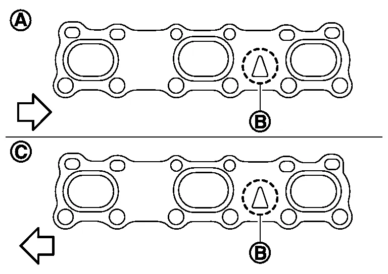
| (A) | : Bank 1 |
| (B) | : Triangle press |
| (C) | : Bank 2 |
| : Engine front |
Install the exhaust manifold (bank 2) nuts and tighten to specification in the order shown.
| : Engine front |
NOTE:
Number 7 and 8 are tightened a second time.
CAUTION:
-
Before installing a heated oxygen sensor or air fuel ratio (A/F) sensor, clean the exhaust manifold threads using the oxygen sensor thread cleaner tool and apply anti-seize lubricant.
Oxygen sensor thread cleaner : — (J-43897-18) -
Do not over-tighten the air fuel ratio (A/F) sensor or heated oxygen sensors. Doing so may cause damage.
Tool numbers : KV10114400 (J-38365) : KV991J0050 (J-44626)
NOTE:
After installation, it is necessary to re-calibrate the electric throttle control actuator as follows:
-
Perform the "Throttle Valve Closed Position Learning" when harness connector of the ECM is disconnected. Refer to Description.
-
Perform the "Accelerator Pedal Released Position Learning" when harness connector of the ECM is disconnected. Refer to Description.
REMOVAL
WARNING:
-
Perform the work when the exhaust system has completely cooled down.
-
When removing the front and rear engine mounting through bolts and nuts, lift the engine up slightly for safety.
NOTE:
When removing components such as hoses, tubes/lines, etc., cap or plug openings to prevent fluid from spilling.
Remove the cowl top and the lower cowl top extension. Refer to Exploded View.
Remove the front wheel and tire (RH) (AWD models only) using a power tool. Refer to Removal and Installation.
Remove the front under cover. Refer to Removal and Installation.
Remove the fender protector side cover (RH) (AWD models only). Refer to Removal and Installation.
Remove transmission air breather hose. Refer to Exploded View.
Remove the front exhaust tube, hanger and heat insulator. Refer to Exploded View.
Remove the propeller shaft and propeller shaft center bearing (AWD models only). Refer to Removal and Installation.
Remove the RH front axle shaft (AWD models only). Refer to Removal and Installation (RH).
Remove the three way catalyst support (bank 1).
Remove heated oxygen sensor 2 (bank 1), air fuel ratio (A/F) sensor 1 (bank 1).disconnect harness connector from each sensor, and remove the harness from the bracket and middle clamp. Remove both heated oxygen sensors and air fuel ratio (A/F) sensors using Tool.
| Tool numbers | : KV10114400 (J-38365) |
| : KV991J0050 (J-44626) |
CAUTION:
-
Be careful not to damage heated oxygen sensors or air fuel ratio (A/F) sensors.
-
Discard any heated oxygen sensor which has been dropped from a height of more than 0.5 m (19.7 in) onto a hard surface such as a concrete floor; replace with a new sensor.
Remove exhaust manifold and three way catalyst heat shields with power tool.
Remove the three way catalyst (bank 1) by loosening the bolts first and then removing the nuts and through bolts.
Loosen the exhaust manifold nuts in the reverse order as shown.

| : Engine front |
NOTE:
Number 7 and 8 are not applicable to removal.
Remove the exhaust manifold (bank 1) and gasket.
INSPECTION AFTER REMOVAL
Surface Distortion
-
Use suitable tools (A/B) to check the flatness of the exhaust manifold mating surfaces.
Limit : 0.3 mm (0.012 in) -
Replace the exhaust manifold if the measurement exceeds specifications.
INSTALLATION
Installation is in the reverse order of removal.
Install the studs in the exhaust manifold (if removed), and tighten to specification.
| Exhaust manifold studs | : 15.4 N·m (1.6 kg-m, 11 ft-lb) |
Install the exhaust manifold gasket in the direction shown.
CAUTION:
Do not reuse exhaust manifold gasket.
| (A) | : Bank 1 |
| (B) | : Triangle press |
| (C) | : Bank 2 |
| : Engine front |
Install the exhaust manifold (bank 1) nuts and tighten to specification in the order shown.
| : Engine front |
NOTE:
Number 7 and 8 are tightened a second time.
CAUTION:
-
Before installing a heated oxygen sensor or air fuel ratio (A/F) sensor, clean the exhaust manifold threads using the oxygen sensor thread cleaner tool and apply anti-seize lubricant.
Oxygen sensor thread cleaner : — (J-43897-18) -
Do not over-tighten the air fuel ratio (A/F) sensor or heated oxygen sensors. Doing so may cause damage.
Tool numbers : KV10114400 (J-38365) : KV991J0050 (J-44626)
 Intake Manifold
Exploded View
1.
Intake manifold
2.
Intake manifold gasket
A.
Refer to Removal and Installation.
Removal and Installation
REMOVALWARNING:
To avoid the danger of being scalded, do not drain the coolant when the engine is hot...
 Oil Pan and Oil Strainer
Exploded View
1.
Oil pan baffle
2.
O-ring
3.
Upper oil pan gasket
4.
Blind plug O-ring
5.
Blind plug
6.
Oil cooler O-ring
7...
Other information:
Nissan Murano (Z52) 2015-2024 Service Manual: Diagnosis and Repair Workflow
Work Flow OVERALL SEQUENCEDETAILED FLOWGET INFORMATION FOR SYMPTOM Get detailed information from the customer about the symptom (the condition and the environment when the incident/malfunction occurred). >> GO TO 2. CONFIRM THE SYMPTOM Try to confirm the symptom described by the customer...
Nissan Murano (Z52) 2015-2024 Service Manual: Brake Fluid
Drain and Refill CAUTION: Do not spill or splash brake fluid on painted surfaces. Brake fluid may damage paint. If brake fluid is splashed on painted areas, wash it away with water immediately. Prior to repair, turn the ignition switch OFF, disconnect the harness connector from the ABS actuator and electric unit (control unit) or negative battery terminal...
Categories
- Manuals Home
- Nissan Murano Owners Manual
- Nissan Murano Service Manual
- Memory storage function (key-link)
- System malfunction
- Tire rotation
- New on site
- Most important about car