Nissan Murano: Compressor / Magnet Clutch
REMOVAL
Remove the compressor. Refer to Removal and Installation.
Remove the center bolt by holding the clutch disc steady using a suitable tool.
Remove the clutch disc and shim.
CAUTION:
Retain all the shims for installation.
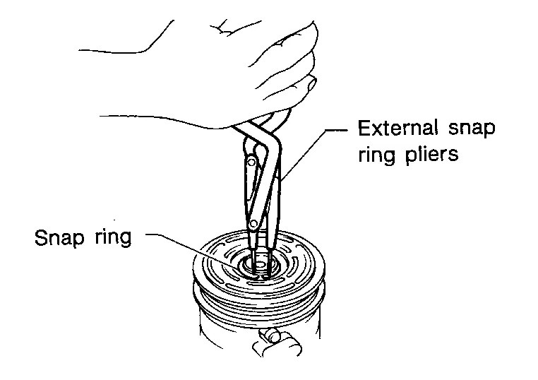
Remove the snap ring using a suitable tool as shown.
Remove the pulley assembly using a suitable tool (A) as shown.
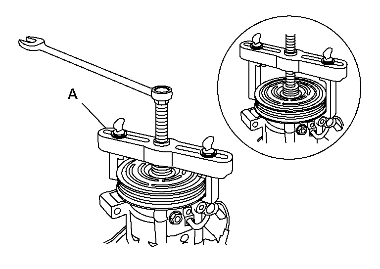
CAUTION:
To prevent deformation of the pulley groove, the puller claws should be hooked under (not into) the pulley groove.
Disconnect the harness connector from the magnet coil.
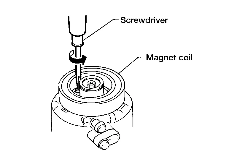
Remove the three magnet coil screws using a suitable tool as shown then remove the magnet coil.
INSPECTION AFTER REMOVAL
-
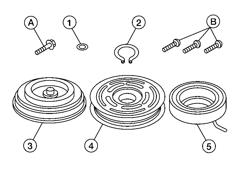
(1): Shim
-
(2): Snap ring
-
(3): Clutch disc
-
(4): Pulley
-
(5): Magnet coil
-
(A): Center bolt
-
(B): Magnet coil screws
Clutch Disc
If the contact surface shows signs of damage due to excessive heat, replace as necessary.
Pulley
Check the appearance of the pulley assembly. If the contact surface of the pulley shows signs of excessive grooving, replace as necessary. The contact surfaces of the pulley assembly should be cleaned with a suitable solvent before installation.
Magnet Coil
Check the magnet coil for a loose connection or cracked insulation. Replace as necessary.
INSTALLATION
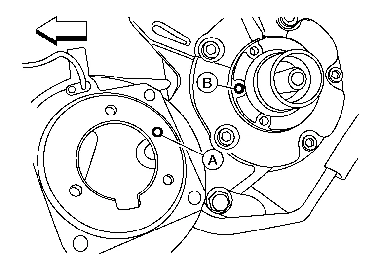
Install the magnet coil by aligning the magnet coil pin (A) with the hole (B) in the compressor front head as shown then install the magnet coil screws.
-
 : Nissan Murano Vehicle rear
CAUTION:
-
Be sure to align the magnet coil pin with the hole in the compressor front head.
Connect the magnet coil harness to the compressor body.
Install the pulley assembly using Tool and a wrench as shown then install the snap ring using a suitable tool.
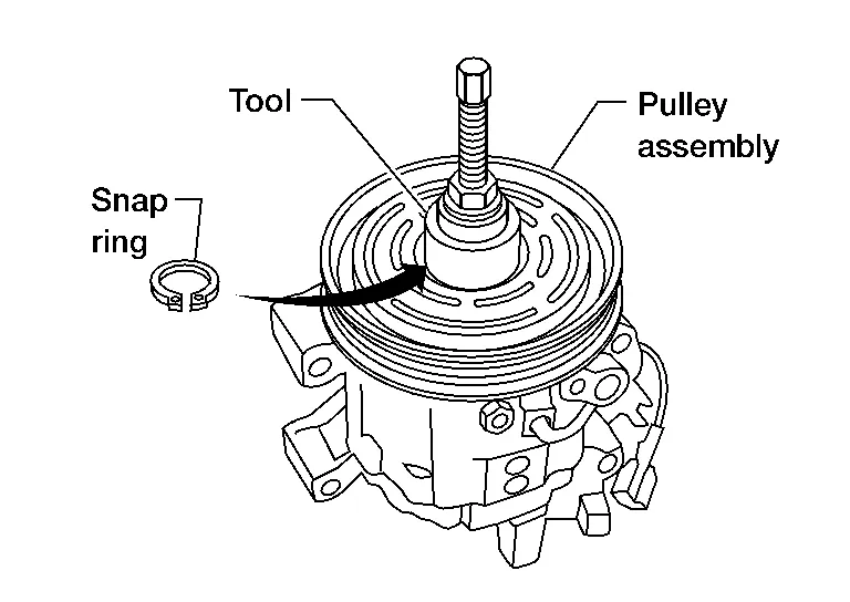
| Tool number | : — (J-38873-A) |
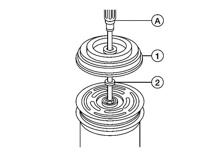
Install the clutch disc (1) on the drive shaft together with all of the original shim(s) (2) using a suitable tool (A).
Install the center bolt using a suitable tool.
Install the compressor. Refer to Removal and Installation.
INSPECTION AFTER INSTALLATION
Check the clearance (B) all the way around between the clutch disc (1) and pulley (2) using a suitable tool (A) as shown.
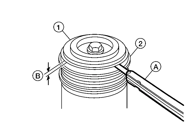
| Clutch disc-to-pulley clearance (B) | : Refer to Compressor. |
If the specified clearance (B) is not obtained, replace the adjusting shims and recheck the clearance (B) as shown.
BREAK-IN OPERATION
When replacing compressor clutch assembly, always conduct the break-in operation. This is done by engaging and disengaging the clutch about 30 times. Break-in operation raises the level of transmitted torque.
 Compressor
Removal and Installation
REMOVALDischarge the refrigerant. Refer to Recycle Refrigerant.
Partially remove the front edge of the front fender protector (RH)...
 Cooler Pipe and Hose
Exploded View
1.
Heating and cooling unit assembly
2.
Internal heat exchanger
3.
High-pressure pipe
4.
Condenser
5.
Compressor
6...
Other information:
Nissan Murano (Z52) 2015-2024 Owners Manual: Engine oil and oil filter recommendations
Selecting the correct oil It is essential to choose the correct grade, quality and viscosity engine oil to ensure satisfactory engine life and performance. For additional information, refer to “Recommended fluids/lubricants and capacities” in this section...
Nissan Murano (Z52) 2015-2024 Service Manual: Engine Room Cover
Exploded View 1. Engine room cover Removal and Installation CAUTION: Do not damage or scratch engine room cover when installing or removing. REMOVALRemove front air duct. Refer to Removal and Installation. Remove engine room cover bolts. Remove engine room cover...
Categories
- Manuals Home
- Nissan Murano Owners Manual
- Nissan Murano Service Manual
- Warning lights
- Fuel recommendation
- All-Wheel Drive (AWD) (if so equipped)
- New on site
- Most important about car
LATCH (Lower Anchors and Tethers for CHildren) system

LATCH system lower anchor locations - bench seat
Your vehicle is equipped with special anchor points that are used with LATCH system compatible child restraints. This system may also be referred to as the ISOFIX or ISOFIX compatible system. With this system, you do not have to use a vehicle seat belt to secure the child restraint unless the combined weight of the child and child restraint exceeds 65 lbs. (29.5 kg). If the combined weight of the child and child restraint is greater than 65 lbs. (29.5 kg), use the vehicle’s seat belt (not the lower anchors) to install the child restraint. Be sure to follow the child restraint manufacturer’s instructions for installation.