Nissan Murano: Compressor / Compressor
REMOVAL
Discharge the refrigerant. Refer to Recycle Refrigerant.
Partially remove the front edge of the front fender protector (RH). Refer to Removal and Installation.
Remove the bolts that retain the oil cooler line brackets to the engine block and reposition the oil cooler line aside. Refer to Removal and Installation.
Remove the drive belt. Refer to Removal and Installation.
Disconnect the harness connector from the compressor.
Disconnect the low-pressure flexible hose from the compressor.
CAUTION:
Cap or wrap the joint of the pipe with suitable material such as vinyl tape to avoid the entry of air.
Disconnect the high-pressure flexible hose from the compressor.
CAUTION:
Cap or wrap the joint of the pipe with suitable material such as vinyl tape to avoid the entry of air.
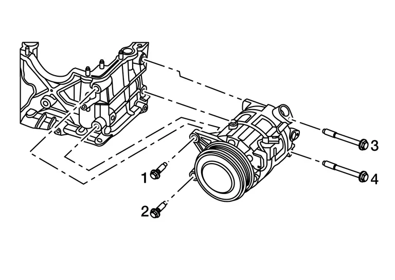
Remove the compressor bolts then remove the compressor.
INSTALLATION
Installation is in the reverse order of removal.
CAUTION:
-
Tighten the compressor bolts in the specified sequence.
-
Do not reuse O-rings.
-
Apply A/C oil to the O-rings on the compressor for installation.
| Bolts (1,2) | : 55.0 N·m (5.6 Kg-m, 41 ft-lb) |
| Bolts (3,4) | : 61.3 N·m (6.3 Kg-m, 45 ft-lb) |
CAUTION:
-
After charging refrigerant, check for leaks. Refer to Leak Test.
-
Check the tension of the drive belt after installing the compressor. Refer to Checking Drive Belt.
 Compressor
Exploded View
Compressor 1.
Compressor
A.
Refer to Removal and Installation.
Magnet Clutch Assembly 1.
Magnet clutch assembly
2...
 Magnet Clutch
Removal and Installation of Compressor Clutch
REMOVALRemove the compressor. Refer to Removal and Installation.
Remove the center bolt by holding the clutch disc steady using a suitable tool...
Other information:
Nissan Murano (Z52) 2015-2024 Service Manual: Accelerator Pedal Released Position Learning
Description Accelerator Pedal Released Position Learning is a function of ECM to learn the fully released position of the accelerator pedal by monitoring the accelerator pedal position sensor output signal. It must be performed each time the harness connector of the accelerator pedal position sensor or ECM is disconnected...
Nissan Murano (Z52) 2015-2024 Service Manual: Working with Grinding the Body Filler (putty)
Danger from Dust If workers continue to inhale dust generated during paint film removal or body filler grinding work for long periods, they may suffer from respiratory insufficiency, which results in pneumoconiosis or asthma. Precautions during Dust Generating Work Workers must use a sander equipped with a dust collecting function...
Categories
- Manuals Home
- Nissan Murano Owners Manual
- Nissan Murano Service Manual
- System malfunction
- All-Wheel Drive (AWD) (if so equipped)
- GAS STATION INFORMATION
- New on site
- Most important about car