
Nissan Murano: Exterior :: Removal and Installation / Front Grille
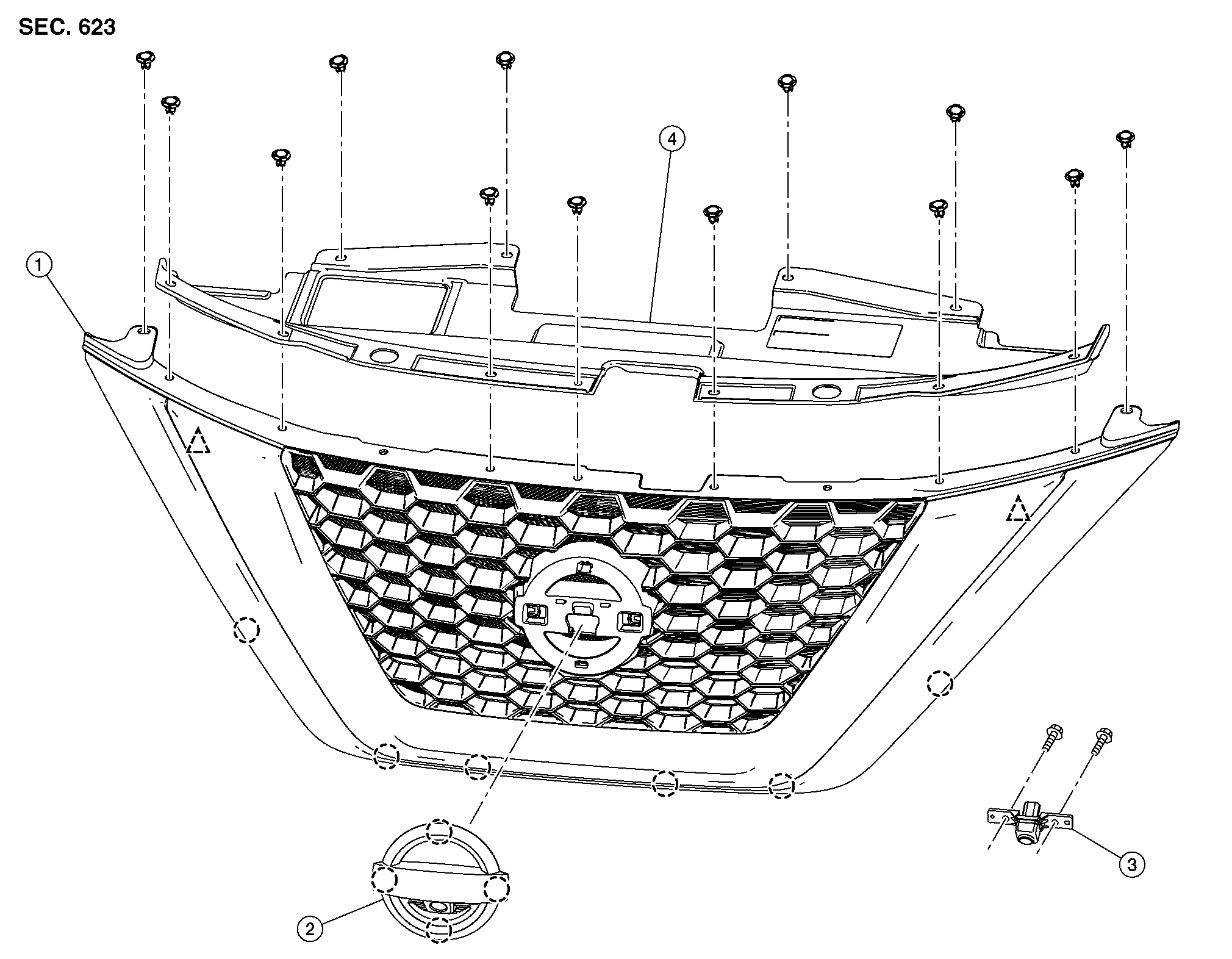
| 1. | Front grille | 2. | Front emblem | 3. | Front camera (if equipped) |
| 4. | Core support cover |  |
Clip |  |
Pawl |
REMOVAL
Remove the core support cover.
Release hood switch harness clip from upper radiator air guide and disconnect harness connector
from hood switch.
Disconnect overflow hose and remove upper radiator air guide (LH/RH).
Release clips then remove front grille.
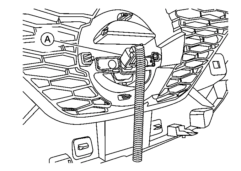
Disconnect the harness connector (A) from the front camera (if equipped).
INSTALLATION
Installation is in the reverse order of removal.
CAUTION:
Perform camera image calibration (with intelligent around view monitor). Refer to Description (WITH DISPLAY AUDIO) or Description (WITH NAVIGATION).
 Rear Bumper
Exploded View
1.
Rear bumper fascia side bracket (LH)
2.
Rear bumper fascia
3.
Rear bumper reinforcement support (LH)
4.
Rear bumper fascia reflector (LH)
5...
 Active Grille Shutter
Exploded View
1.
Active grille shutter
2.
Radiator core support
Front
Removal and Installation
REMOVALRemove front bumper fascia. Refer to Removal and Installation...
Other information:
Nissan Murano (Z52) 2015-2024 Service Manual: B2128 Uart Comm
DTC Description DTC DETECTION LOGIC DTC No. CONSULT screen terms (Trouble diagnosis content) DTC Detection Condition B2128 UART COMM (Universal asynchronous receiver transmitter communication) Diagnosis condition — Signal (terminal) — Threshold Communication between driver seat control unit and automatic drive positioner control unit is interrupted...
Nissan Murano (Z52) 2015-2024 Service Manual: Action Test
Description Always perform the ICC system action test to check that the ICC system operates normally after replacing the distance sensor (ICC sensor) or repairing any ICC system malfunction.CAUTION: Always drive safely when performing the action test...
Categories
- Manuals Home
- Nissan Murano Owners Manual
- Nissan Murano Service Manual
- High Beam Assist (if so equipped)
- Checking engine oil level
- Shift lock release
- New on site
- Most important about car
Luggage hooks

When securing items using luggage hooks located on the back of the seat or side finisher do not apply a load over more than 6.5 lbs. (29 N) to a single hook.
The luggage hooks that are located on the floor should have loads less than 110 lbs. (490 N) to a single hook.
