Nissan Murano: Exterior :: Removal and Installation / Rear Bumper
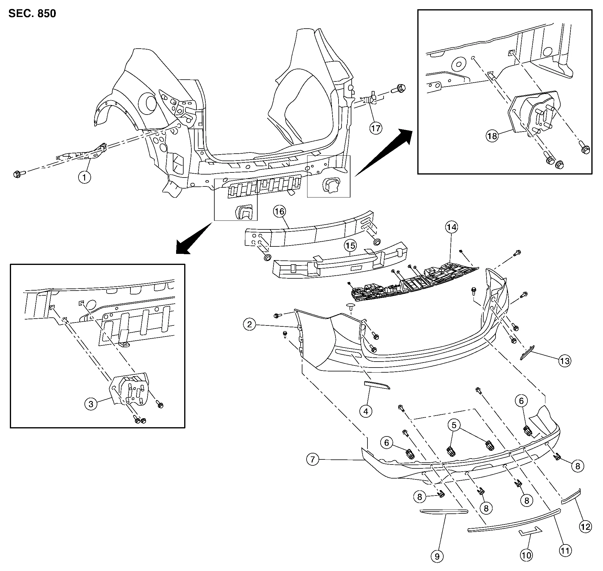
| 1. | Rear bumper fascia side bracket (LH) | 2. | Rear bumper fascia | 3. | Rear bumper reinforcement support (LH) |
| 4. | Rear bumper fascia reflector (LH) | 5. | Sonar sensor (inner) | 6. | Sonar sensor (outer) |
| 7. | Rear bumper fascia lower | 8. | Sonar finisher | 9. | Rear bumper fascia molding (LH) |
| 10. | Rear bumper fascia finisher | 11. | Rear bumper fascia molding center | 12. | Rear bumper fascia molding (RH) |
| 13. | Rear bumper fascia reflector (RH) | 14. | Motion activated back door bracket | 15. | Rear energy absorber |
| 16. | Rear bumper reinforcement | 17. | Rear bumper fascia side bracket (RH) | 18. | Rear bumper reinforcement support (RH) |
CAUTION:
Rear bumper fascia is made of resin. Use care when handling to prevent damage. Avoid contact with oily substances.
REMOVAL
Remove rear combination lamps (body side) (LH/RH). Refer to Removal and Installation.
Partially remove rear over fender (LH/RH). Refer to Exploded View.
Remove rear bumper fascia upper screws.
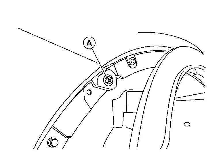
Remove rear bumper fascia screw (A) (LH/RH).
Disconnect motion activated back door control unit harness connector (if equipped).
Disconnect sonar sensor harness connectors.
Release rear bumper fascia pawls from the rear bumper fascia side bracket (LH/RH) and remove.
CAUTION:
When removing rear bumper fascia, two people are required to avoid damaging.
Remove rear energy absorber.
Remove rear bumper reinforcement nuts (LH/RH) then remove rear bumper reinforcement.
Remove rear bumper reinforcement support bolts (LH/RH) then remove rear bumper reinforcement support (LH/RH).
INSTALLATION
Installation is in the reverse order of removal.
 NOTE:
NOTE:
After installation, perform the following action tests to confirm proper system operation:
-
Blind Spot Warning: Refer to Description.
-
Rear Cross Traffic Alert (RCTA): Refer to Description.
NOTE:
-
The following table shows the specified values for checking normal installation specifications.
-
Fitting adjustment cannot be performed.
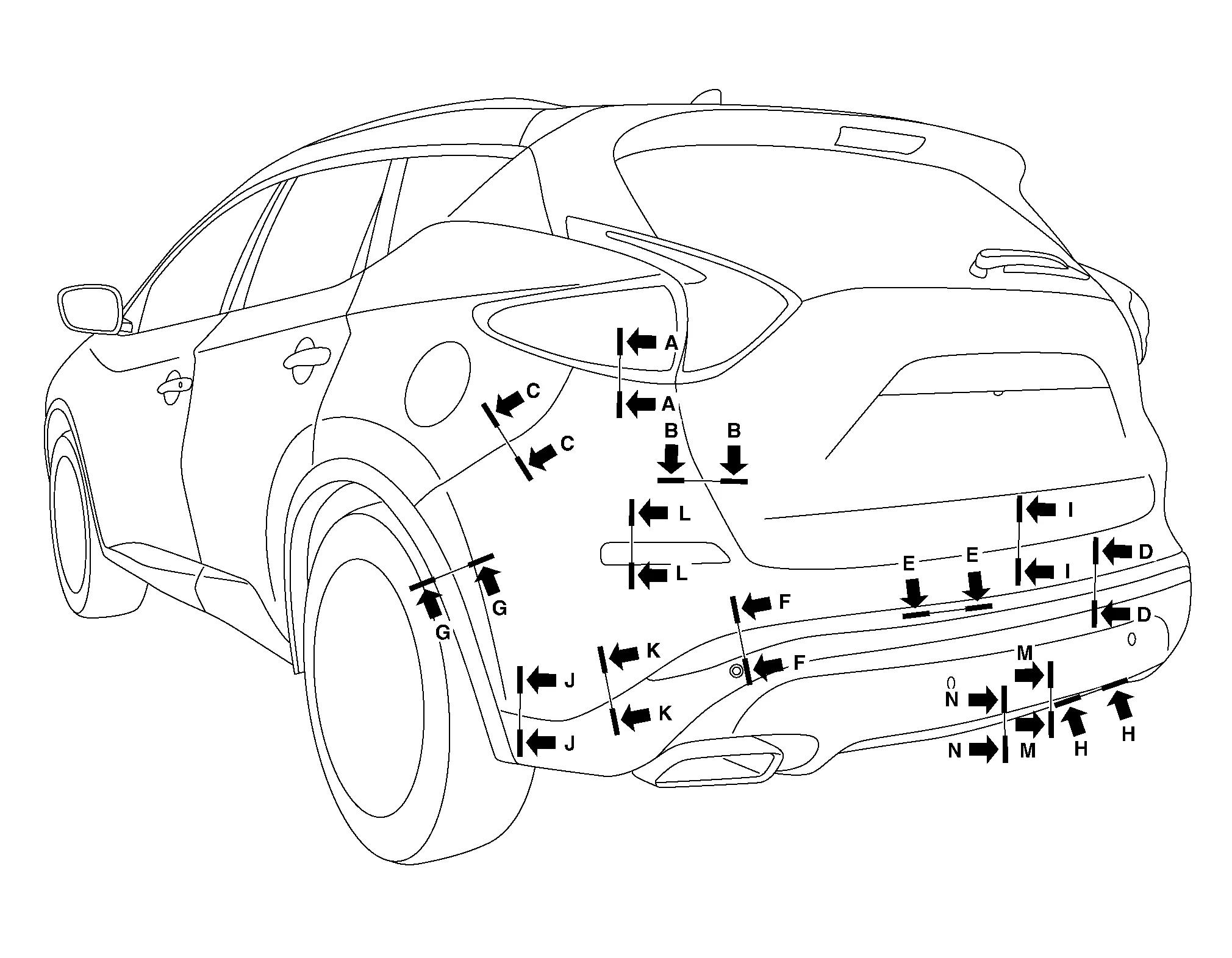
| Section | Measurement | Minimum | Target Value | Maximum |
|---|---|---|---|---|
| A-A | Clearance | 0.1 (0.004) | 1.5 (0.06) | 2.9 (0.11) |
| B-B | Clearance | 4.1 (0.16) | 6.0 (0.24) | 7.9 (0.31) |
| Surface height | -1.4 (-0.06) | 0.5 (0.02) | 2.4 (0.09) | |
| C-C | Clearance | 0.0 (0.00) | 0.3 (0.01) | 1.0 (0.04) |
| Surface height | -0.1 (-0.004) | 0.7 (0.03) | 1.5 (0.06) | |
| D-D | Clearance | 0.0 (0.00) | 1.0 (0.04) | 2.0 (0.08) |
| E-E | Clearance | 0.1 (0.004) | 1.2 (0.05) | 2.3 (0.09) |
| Surface height | -1.0 (-0.04) | 0.0 (0.00) | 1.0 (0.04) | |
| F-F | Clearance | 0.0 (0.00) | 1.0 (0.04) | 2.0 (0.08) |
| G-G | Clearance | 0.0 (0.00) | 0.5 (0.02) | 1.5 (0.06) |
| H-H | Clearance | 0.00 (0.00) | 1.0 (0.04) | 2.0 (0.08) |
| I-I | Clearance | 6.1 (0.24) | 8.0 (0.31) | 9.9 (0.39) |
| J-J | Clearance | 0.0 (0.00) | 0.0 (0.00) | 0.7 (0.03) |
| K-K | Clearance | 0.3 (0.01) | 1.0 (0.04) | 1.7 (0.07) |
| L-L | Clearance | 0.5 (0.02) | 1.5 (0.06) | 2.5 (0.10) |
| M-M | Clearance | 0.5 (0.02) | 1.0 (0.04) | 2.5 (0.10) |
| N-N | Clearance | 0.00 (0.00) | 1.0 (0.04) | 2.0 (0.08) |
 Front Bumper
Exploded View
1.
Front bumper fascia side bracket (RH)
2.
Front bumper side retainer (RH)
3.
Front bumper reinforcement bracket (RH)
4.
Front bumper reinforcement
5...
 Front Grille
Exploded View
1.
Front grille
2.
Front emblem
3.
Front camera (if equipped)
4.
Core support cover
Clip
Pawl
Removal and Installation
REMOVALRemove the core support cover...
Other information:
Nissan Murano (Z52) 2015-2024 Service Manual: Remote Keyless Entry Function
System Description SYSTEM DIAGRAMSYSTEM DESCRIPTIONThe Intelligent Key has the same functions as the remote control entry system. Therefore, it can be used in the same manner as the remote controller by operating the door lock/unlock button.INPUT SIGNAL AND OUTPUT SIGNAL Signal name Input Output Description Key ID signal Remote keyless entry receiver BCM The BCM receives key ID signal inputs and activates the actuators accordingly...
Nissan Murano (Z52) 2015-2024 Service Manual: Front and Rear Washer Motor
Exploded View 1. Washer tank 2. Front and rear washer motor 3. Washer fluid level switch Removal and Installation REMOVALRemove the front fender protector (RH). Refer to Removal and Installation...
Categories
- Manuals Home
- Nissan Murano Owners Manual
- Nissan Murano Service Manual
- Passenger compartment
- High Beam Assist (if so equipped)
- Memory storage function (key-link)
- New on site
- Most important about car
Unfastening the seat belts. Checking seat belt operation
Unfastening the seat belts

To unfasten the seat belt, press the button
on the buckle  . The seat belt
automatically
retracts.
. The seat belt
automatically
retracts.