Nissan Murano: Front Suspension :: Removal and Installation / Front Coil Spring and Strut
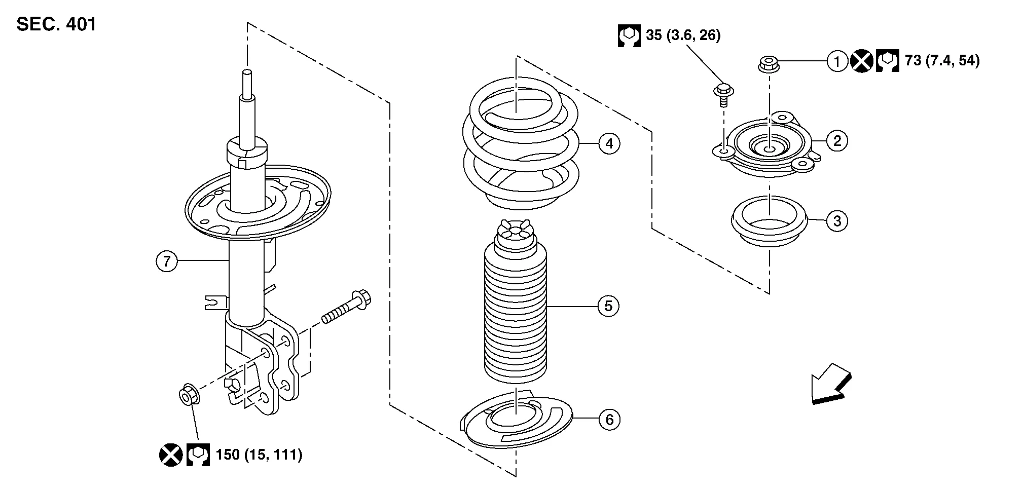
| 1. | Piston rod lock nut | 2. | Strut mount insulator | 3. | Strut mount bearing |
| 4. | Front coil spring | 5. | Bound bumper | 6. | Lower rubber seat |
| 7. | Strut | Front |
REMOVAL
Remove strut bolt access panel from cowl top.
Remove strut bolt grommet from cowl top extension.
Remove strut mount insulator bolts using power tool.
Remove wheel and tire using power tool. Refer to Removal and Installation.
Remove bolt (A) and separate front wheel sensor from steering knuckle. Refer to Exploded View.

CAUTION:
-
Failure to separate front wheel sensor from steering knuckle may result in damage to front wheel sensor.
-
Pull out front wheel sensor being careful to turn it as little as possible. Do not pull on wheel sensor harness.
Separate front wheel sensor harness from front coil spring and strut.
Remove brake hose lock plate (A).
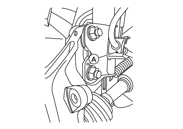
Remove stabilizer connecting rod nut (A) from front coil spring and strut. Position stabilizer connecting rod aside. Refer to Exploded View.

Remove lower strut nuts and bolts using power tool.
Remove front coil spring and strut.
INSPECTION AFTER REMOVAL
Strut
Check the following items, and replace the parts if necessary.
-
Strut for deformation, cracks or damage
-
Piston rod for damage, uneven wear or distortion
-
Oil leakage
Strut Mount Insulator, Strut Mount Bearing, and Rubber Parts Inspection
Check strut mount insulator and strut mount bearing for cracks. Check rubber parts for wear. Replace parts if necessary.
Front Coil Spring
Check front coil spring for cracks, wear, or damage. Replace front coil spring if necessary.
INSTALLATION
Installation is in reverse order of removal.
CAUTION:
Do not reuse lower strut nuts.
-
Be sure tab (A) on strut mount insulator is positioned as shown.
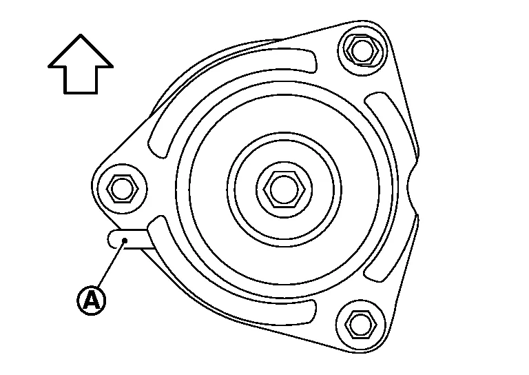

: Front -
Be sure lower strut nuts (A) are facing front of Nissan Murano vehicle.
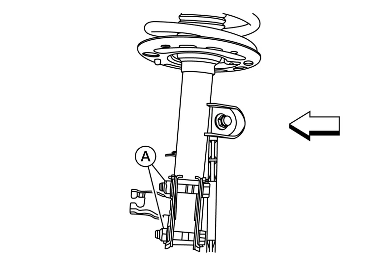
: Front -
Check wheel alignment. Refer to Inspection.
-
Adjust neutral position of steering angle sensor. Refer to Description.
-
After replacing the strut, follow disposal procedure to discard old strut. Refer to Disposal.
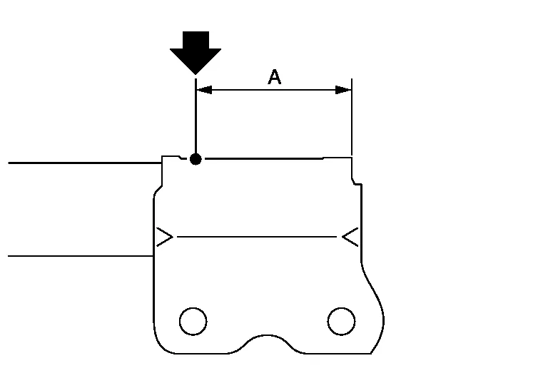
Set strut horizontally with piston rod fully extended.
Drill a 2 – 3 mm (0.08 – 0.12 in) hole at position ( ) from top as shown to release gas gradually.
CAUTION:
-
Wear eye protection (safety glasses).
-
Wear gloves.
-
Be careful with metal chips or oil blown out by compressed gas.
 NOTE:
NOTE:
-
Drill vertically in this direction (
 ) directly to outer tube avoiding brackets.
 -
The gas is clear, colorless, odorless, and harmless.
| (A) | : 20 – 30 mm (0.79 – 1.18 in) |
Position drilled hole downward and drain oil by moving piston rod several times.
CAUTION:
Dispose of drained oil according to the law and local regulations.

 Transverse Link
Exploded View
1.
Transverse link
2.
Front suspension member
Removal and Installation
REMOVALRemove steering knuckle with wheel hub and bearing...
Other information:
Nissan Murano (Z52) 2015-2024 Owners Manual: System malfunction
If the I-FCW system malfunctions, it will be turned off automatically, a chime will sound, the AEB system warning light (orange) will illuminate and the warning message [Malfunction] will appear in the vehicle information display. Action to take If the warning light (orange) comes on, stop the vehicle in a safe location, turn the engine off and restart the engine...
Nissan Murano (Z52) 2015-2024 Service Manual: Front Camera Unit
Values on the Diagnosis Tool VALUE ON THE DIAGNOSIS TOOLNOTE: The following table includes information (items) inapplicable to this Nissan Murano vehicle. For information (items) applicable to this vehicle, refer to CONSULT display items. Monitor item Condition Value/Status CAMERA HIGH TEMP When the temperature around lane camera unit is adequate NORMAL When the temperate around the lane camera unit is high HIGH WIPER Ignition switch ON Wiper position is High Hi Wiper position is Low Lo Wiper position is OFF Off TURN SIGNAL Turn signal lamp LH and RH blinking LH&RH Turn signal lamp LH blinking LH Turn signal lamp RH blinking RH Turn signal lamps OFF Off Nissan Murano Vehicle SPEED While drive km/h DRIVER ASSIST SYSTEM SET NOTE: The item is displayed, but it is not used...
Categories
- Manuals Home
- Nissan Murano Owners Manual
- Nissan Murano Service Manual
- Fuel recommendation
- Vehicle Dynamic Control (VDC) OFF switch
- Turning the AEB system on/off
- New on site
- Most important about car
Fuel gauge

The gauge indicates the approximate fuel level in the tank.
The gauge may move slightly during braking, turning, acceleration, or going up or down hills.
The gauge needle returns to 0 (Empty) after the ignition switch is placed in the OFF position.