Nissan Murano: Ecu Diagnosis Information / Front Camera Unit
VALUE ON THE DIAGNOSIS TOOL
 NOTE:
NOTE:
The following table includes information (items) inapplicable to this Nissan Murano vehicle. For information (items) applicable to this vehicle, refer to CONSULT display items.
| Monitor item | Condition | Value/Status | |
|---|---|---|---|
| CAMERA HIGH TEMP | When the temperature around lane camera unit is adequate | NORMAL | |
| When the temperate around the lane camera unit is high | HIGH | ||
| WIPER | Ignition switch ON | Wiper position is High | Hi |
| Wiper position is Low | Lo | ||
| Wiper position is OFF | Off | ||
| TURN SIGNAL | Turn signal lamp LH and RH blinking | LH&RH | |
| Turn signal lamp LH blinking | LH | ||
| Turn signal lamp RH blinking | RH | ||
| Turn signal lamps OFF | Off | ||
| Nissan Murano Vehicle SPEED | While drive | km/h | |
| DRIVER ASSIST SYSTEM SET |
The item is displayed, but it is not used. |
NO REQ | |
| BRAKE OPERATION STATUS | When brake pedal is depressed | Off | |
| When brake pedal is depressed | On | ||
| When brake pedal is securely depressed | CNFRM | ||
| When brake pedal operation is not judged | UNKWN | ||
| AIMING DONE | Camera aiming is completed | finished | |
| Camera aiming is not adjusted | not finished | ||
| AIMING RESULT | Camera aiming is completed | OK | |
| Camera aiming is not completed | NOK | ||
| STEERING ANGLE | When driving straight | Approx. 0.0 deg | |
| When steering wheel is steered | Value of steering angle (deg) | ||
| YAW RATE | Nissan Murano Vehicle stopped | Approx. 0 deg/s | |
| Turning right | Negative value | ||
| Turning left | Positive value | ||
| FCTRY AIM YAW | Camera aiming is completed | 0 ± 3.0 deg | |
| FCTRY AIM ROL | Camera aiming is completed | 0 ± 3.0 deg | |
| FCTRY AIM PIT | Camera aiming is completed | 0 ± 3.0 deg | |
| LDW FUNCTION | When LDW function is ON | NORMAL | |
| When LDW function malfunction is detected | MALF | ||
| LDW SETTING DISPLAY |
The item is displayed, but it is not used. |
NTHNG | |
| DRIVER ASSIST SYSTEM BZZR |
The item is displayed, but it is not used. |
NO REQ | |
| LDW LEFT | Left side lane maker is not detected | Off | |
| Left side lane maker is detected | On | ||
| LDW RIGHT | Right side lane maker is not detected | Off | |
| Right side lane maker is detected | On | ||
| LDW STATUS DISPLAY |
The item is displayed, but it is not used. |
Off | |
| HBA FUNCTION |
The item is displayed, but it is not used. |
— | |
| DISTANCE | Drive the Nissan Murano vehicle and AEB system ON | When the lane camera detects an object to be controlled | Displays distance from Nissan Murano vehicle ahead |
| When the lane camera does not detect an object to be controlled | 0.0 m | ||
| RELATIVE SPEED | Drive the Nissan Murano vehicle and AEB system ON | When the lane camera detects an object to be controlled | Displays relative velocity |
| When the lane camera does not detect an object to be controlled | 0.0 m/s | ||
| Initialization ECU | Power switch ON | When initialization of the lane camera unit is not completed | INCOMP |
| When initialization of the lane camera unit is completed | COMP | ||
| HBA REQUEST |
The item is displayed, but it is not used. |
— | |
| LOW BEAM STATUS |
The item is displayed, but it is not used. |
— | |
| HIGH BEAM STATUS |
The item is displayed, but it is not used. |
— | |
| NO-ENTRY SIGN DISPLAY |
The item is displayed, but it is not used. |
— | |
TERMINAL LAYOUT
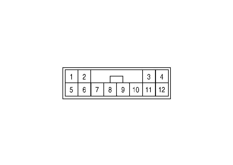
PHYSICAL VALUES
|
Terminal No. (Wire color) | Description | Condition |
Value (Approx.) | ||
|---|---|---|---|---|---|
| + | – | Signal name | Input/Output | ||
|
1 (B) |
Ground | Ground | Output | — | 0 V |
|
3 (BG) |
Ignition power supply | Input | Ignition switch ON | Battery voltage | |
|
5 (L) |
ITS communication high | — | — | — | |
|
6 (Y) |
ITS communication low | — | — | — | |
Refer to Fail-safe (Lane Camera Unit).
If multiple DTCs are detected simultaneously, check them one by one depending on the following DTC inspection priority chart.
| Priority | Detected items (DTC) |
|---|---|
| 1 |
|
| 2 |
|
| 3 |
|
×: Applicable
| DTC | Warning display | Fail-safe | |||||
|---|---|---|---|---|---|---|---|
| LDW system warning | I-LI system warning | LDW | I-LI | TSR | Reference | ||
| C1B00-4B | CAMERA UNIT MALF | ON | ON | × | × | × | DTC Description |
| C1B00-04 | CAMERA UNIT MALF | ON | ON | × | × | × | DTC Description |
| C1B00-41 | CAMERA UNIT MALF | ON | ON | × | × | × | DTC Description |
| C1B00-44 | CAMERA UNIT MALF | ON | ON | × | × | × | DTC Description |
| C1B00-45 | CAMERA UNIT MALF | ON | ON | × | × | × | DTC Description |
| C1B00-46 | CAMERA UNIT MALF | ON | ON | × | × | × | DTC Description |
| C1B00-47 | CAMERA UNIT MALF | ON | ON | × | × | × | DTC Description |
| C1B00-48 | CAMERA UNIT MALF | ON | ON | × | × | × | DTC Description |
| C1B00-49 | CAMERA UNIT MALF | ON | ON | × | × | × | DTC Description |
| C1B00-52 | CAMERA UNIT MALF | ON | ON | × | × | × | DTC Description |
| C1B00-56 | CAMERA UNIT MALF | ON | ON | × | × | × | DTC Description |
| C1B00-57 | CAMERA UNIT MALF | ON | ON | × | × | × | DTC Description |
| C1B00-87 | CAMERA UNIT MALF | ON | ON | × | × | × | DTC Description |
| C1B01-54 | CAMERA AIMING INCMP | ON | ON | × | × | × | DTC Description |
| C1B09-17 | POWER SUPPLY CIRC | ON | ON | × | × | × | DTC Description |
| C1B0A-16 | POWER SUPPLY CIRC 2 | ON | ON | × | × | × | DTC Description |
| U1000-01 | CAN COMM CIRCUIT | ON | ON | × | × | × | DTC Description |
| U1010-49 | CONTROL UNIT (CAN) | ON | ON | × | × | × | DTC Description |
| U0104-00 | ADAS CAN CIRC | ON | ON | × | × | — | DTC Description |
| U0122-00 | VDC CAN CIRC1 (LDP) | ON | ON | × | × | × | DTC Description |
| U0126–00 | STRG SEN CAN CIR1 | ON | ON | × | × | × | DTC Description |
| U0405-83 | ADAS CAN CIR 2 | ON | ON | × | × | — | DTC Description |
| U0428–83 | STRG SEN CAN CIR2 | ON | ON | × | × | — | DTC Description |
| U1321-55 | CONFIGURATION DATA ERROR | ON | ON | × | × | — | DTC Description |
| U1322-01 | CONFIG WRITE ERROR | ON | ON | × | × | — | DTC Description |
 Side Radar Lh
Values on the Diagnosis Tool
CONSULT MONITOR ITEM Monitor Item Condition Value/Status
BSW/CTA WARN STATUS
BSW system is normal
On
BSW system is malfunctioning
Off
CTA SYSTEM ON
CTA system is ON
On
CTA system is OFF
Off
BSW STATUS
BSW system is ON
On
BSW system is OFF
Off
VHCL SPD SE
Indicates current Nissan Murano vehicle speed
km/h
TURN SIGNAL
Left/right turn signal is ON
On
Left/right turn signal is OFF
Off
SHIFT POSITION
Shows the position of the transmission range switch
P/R/N/D
LUMINANCE(LEFT)
Shows radar left luminance level
Hi/Lo
LUMINANCE (RIGHT)
Shows radar right luminance level
Hi/Lo
Reference Value
TERMINAL LAYOUTPHYSICAL VALUES
Terminal No...

Other information:
Nissan Murano (Z52) 2015-2024 Service Manual: B1305 Control Unit Internal Fault
DTC Description DTC DETECTION LOGIC DTC No. CONSULT screen terms (Trouble diagnosis content) DTC detection condition B1305–04 Control unit internal error (AV control unit internal fault) [—] Diagnosis condition When ignition switch is ON...
Nissan Murano (Z52) 2015-2024 Service Manual: Center Console Assembly
Exploded View 1. Center console side finisher (RH) 2. Center console side finisher (LH) 3. Center console lower side finisher (LH) 4. Center console reinforcement bracket 5. Mood lamp [front console LH (if equipped)] 6. Mood lamp lens [front console LH (if equipped)] 7...
Categories
- Manuals Home
- Nissan Murano Owners Manual
- Nissan Murano Service Manual
- Memory storage function (key-link)
- Checking engine oil level
- All-Wheel Drive (AWD) (if so equipped)
- New on site
- Most important about car
Fuel gauge

The gauge indicates the approximate fuel level in the tank.
The gauge may move slightly during braking, turning, acceleration, or going up or down hills.
The gauge needle returns to 0 (Empty) after the ignition switch is placed in the OFF position.