Nissan Murano: Front Suspension :: Removal and Installation / Transverse Link
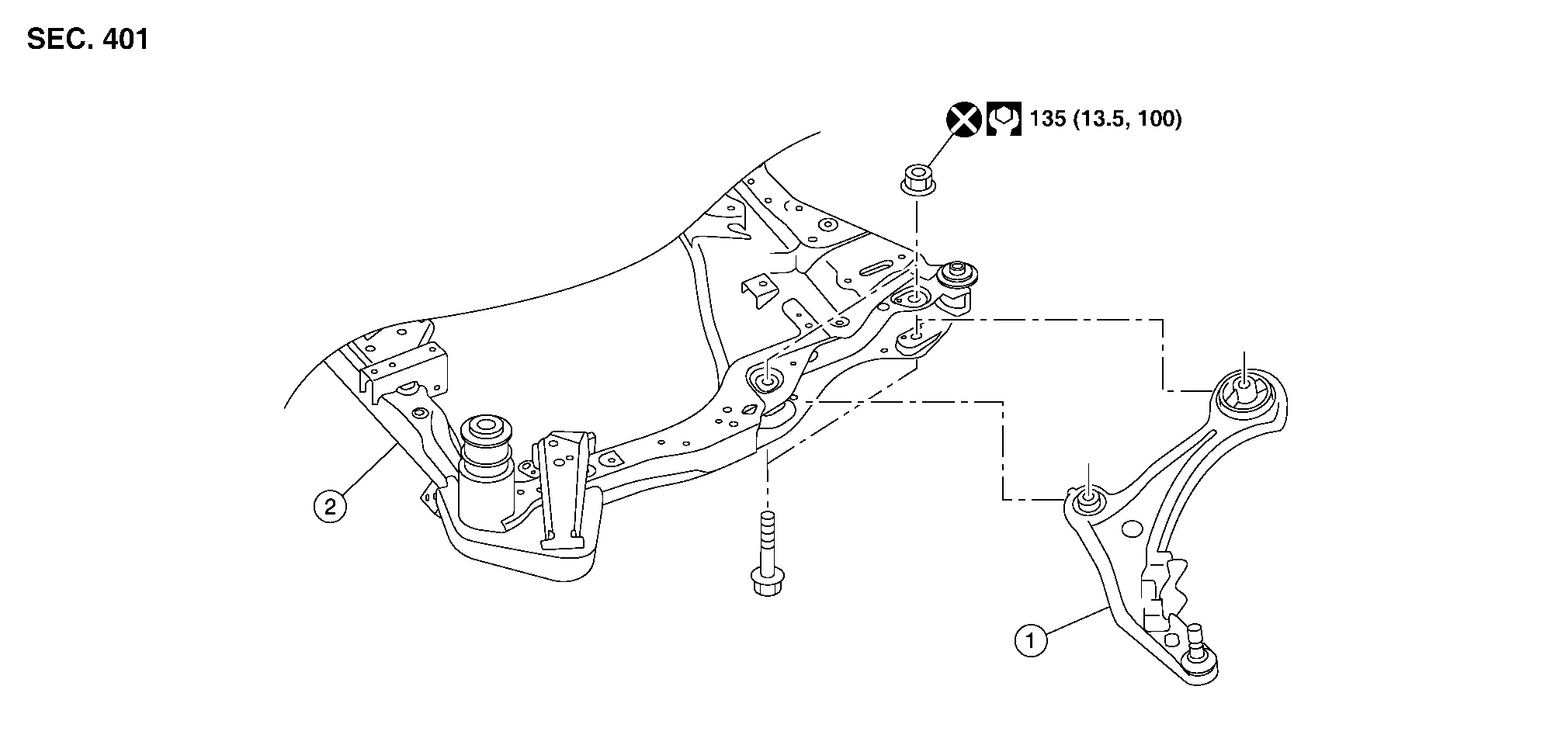
| 1. | Transverse link | 2. | Front suspension member |
REMOVAL
Remove steering knuckle with wheel hub and bearing. Refer to Removal and Installation.
Remove transverse link nuts and bolts from suspension member.
Remove transverse link from suspension member.
INSPECTION AFTER REMOVAL
TRANSVERSE LINK
-
Transverse link for deformation, cracks or damage.
-
Bushing for complete separation. (If completely separated, inner metal can be pulled out from transverse link.)
-
Bushing for leakage.
-
Ball joint boot for cracks or other damage, and also for grease leakage.
Swinging Torque Inspection
-
Move ball joint at least ten times by hand to check for smooth movement.
-
Hook Tool (A) on ball joint at pinch bolt location. Confirm measurement value is within specifications when ball joint begins moving.
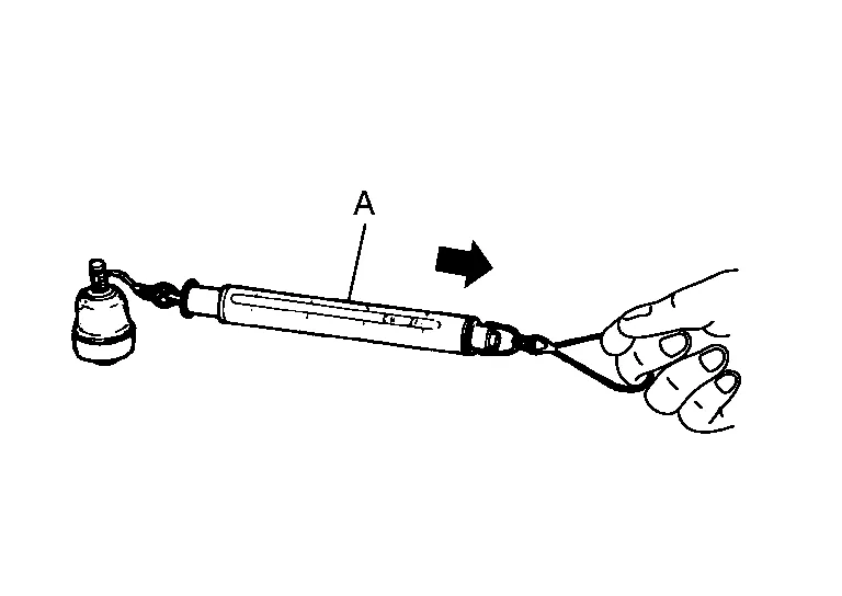
Tool number : – (J-44372) Swinging torque : Refer to Ball Joint. -
If swinging torque exceeds standard range, replace transverse link.
-
Rotating Torque Inspection
-
Move ball joint at least ten times by hand to check for smooth movement.
-
Confirm measurement value is within specifications when ball joint begins rotating.
Rotating torque : Refer to Ball Joint. -
If rotating torque exceeds standard range, replace transverse link.
-
Axial End Play Inspection
-
Move ball joint at least ten times by hand to check for smooth movement.
-
Move tip of ball joint in axial direction to check for looseness.
-
If there is axial end play, replace transverse link assembly.
-
INSTALLATION
Installation is in reverse order of removal.
CAUTION:
-
Do not reuse transverse link nuts at front suspension member.
-
Do not reuse steering knuckle lower nut.
-
Perform final tightening of bolts and nuts at front suspension member under unladen conditions with tires on level ground.
-
Check wheel alignment. Refer to Inspection.
-
Adjust neutral position of steering angle sensor. Refer to Description.
 Front Coil Spring and Strut
Exploded View
1.
Piston rod lock nut
2.
Strut mount insulator
3.
Strut mount bearing
4.
Front coil spring
5.
Bound bumper
6.
Lower rubber seat
7...
 Front Stabilizer
Exploded View
1.
Stabilizer
2.
Front suspension member
3.
Stabilizer connecting rod
4.
Stabilizer bushing
5.
Stabilizer clamp
Removal and Installation
REMOVALRemove front wheels and tires using power tool...
Other information:
Nissan Murano (Z52) 2015-2024 Service Manual: I-Li
System Description SYSTEM DIAGRAMADAS CONTROL UNIT INPUT/OUTPUT SIGNAL ITEMInput Signal Item Transmit unit Signal name Description ECM CAN communication Brake pedal position switch signal Receives Brake pedal position switch state Accelerator pedal position signal Receives accelerator pedal position (angle) Stop lamp switch signal Receives stop lamp switch state Engine speed signal Receives engine speed TCM CAN communication Input speed signal Receives the number of revolutions of input shaft Current gear position signal Receives a current gear position Shift position signal Receives a selector lever position Output shaft revolution signal Receives the number of revolutions of output shaft ABS actuator and electric unit (control unit) CAN communication ABS malfunction signal Receives a malfunction state of ABS ABS operation signal Receives an operational state of ABS TCS malfunction signal Receives a malfunction state of TCS TCS operation signal Receives an operational state of TCS VDC OFF switch signal Receives an ON/OFF state of VDC VDC malfunction signal Receives a malfunction state of VDC VDC operation signal Receives an operational state of VDC Nissan Murano Vehicle speed signal (ABS) Receives wheel speeds of four wheels Yaw rate signal Receives yaw rate acting on the Nissan Murano vehicle Side G sensor signal Receives lateral G acting on the Nissan Murano vehicle Combination meter CAN communication Parking brake switch signal Receives an operational state of the parking brake System selection signal Receives a selection state of each item in "Driver Assistance" BCM CAN communication Turn indicator signal Receives an operational state of the turn signal lamp and the hazard lamp Steering angle sensor CAN communication Steering angle sensor malfunction signal Receives a malfunction state of steering angle sensor Steering angle sensor signal Receives the number of revolutions, turning direction of the steering wheel Steering angle speed signal Receives the turning angle speed of the steering wheel Lane intervention switch Lane intervention switch signal Receives an ON/OFF state of the lane intervention switch Lane camera unit ITS communication Detected lane condition signal Receives detection results of lane marker Output Signal Item Reception unit Signal name Description ABS actuator and electric unit (control unit) CAN communication Target yaw moment signal Transmits a target yaw moment signal to generate yaw moment to the Nissan Murano vehicle Combination meter CAN communication Intelligent Lane Intervention ON indicator lamp signal Transmits an Intelligent Lane Intervention ON indicator lamp signal to turn ON the Intelligent Lane Intervention ON indicator lamp Lane departure warning lamp signal Transmits an lane departure warning lamp signal to turn ON the lane departure warning lamp Lane camera unit ITS communication Nissan Murano Vehicle speed signal Transmits a vehicle speed calculated by the ADAS control unit Turn indicator signal Transmits a turn indicator signal received from BCM Steering assist system ON indicator Steering assist system ON indicator signal Turns ON the steering assist system ON indicator Intelligent Lane Intervention system ON indicator Intelligent Lane Intervention system ON indicator signal Turns ON the Intelligent Lane Intervention system ON indicator Warning system buzzer Warning buzzer signal Activates warning system buzzer...
Nissan Murano (Z52) 2015-2024 Service Manual: Wheel Hub
On-vehicle Service Check axle and suspension parts for excessive play, wear or damage. Move the wheel as shown to check for excessive play. Inspection Check wheel hub bearing axial end play. Axial end play : Refer to Wheel Bearing. Check that wheel hub bearings operate smoothly...
Categories
- Manuals Home
- Nissan Murano Owners Manual
- Nissan Murano Service Manual
- Tire rotation
- Passenger compartment
- How to enable/disable the LDW system
- New on site
- Most important about car
Front manual seat adjustment (if so equipped)
Your vehicle seats can be adjusted manually. For additional information about adjusting the seats, refer to the steps outlined in this section.
Forward and backward
