Nissan Murano: Unit Disassembly and Assembly / Electric Controlled Coupling
 |
Stud bolt |  |
Connector bracket |  |
Reamer bolt |
 |
Electric controlled coupling assembly |  |
Wave spring |  |
Drive pinion oil seal |
 |
Drive pinion lock nut |  |
Pinion front bearing |  |
Gear carrier |
 |
Collapsible spacer |  |
Drive pinion adjusting shim |  |
Pinion rear bearing |
 |
Drive pinion |  |
Drive gear |  |
Differential case |
 |
Side bearing |  |
Side bearing adjusting shim |  |
Side oil seal |
 |
Rear cover |  |
Stud bolt |  |
Gasket |
 |
Drain plug |  |
Filler plug |  |
Pinion mate thrust washer |
 |
Pinion mate gear |  |
Side gear thrust washer |  |
Side gear |
 |
Pinion mate shaft |  |
Lock pin | ||
 |
Oil seal lip |  |
Screw hole | ||
 : N·m (kg-m, in-lb) : N·m (kg-m, in-lb) |
|||||
 : N·m (kg-m, ft-lb) : N·m (kg-m, ft-lb) |
|||||
 : Always replace after every disassembly. : Always replace after every disassembly. |
|||||
 : Select with proper thickness. : Select with proper thickness. |
|||||
 : Apply gear oil. : Apply gear oil. |
|||||
| *: Apply anti-corrosion oil. |
|||||
 : Apply multi purpose grease. : Apply multi purpose grease. |
|||||
 : Apply Genuine Silicone RTV or equivalent. Refer to Recommended Chemical Products and Sealants. : Apply Genuine Silicone RTV or equivalent. Refer to Recommended Chemical Products and Sealants. |
|||||
 : Apply Genuine High Strength Thread Locking Sealant or equivalent. Refer to Recommended Chemical Products and Sealants. : Apply Genuine High Strength Thread Locking Sealant or equivalent. Refer to Recommended Chemical Products and Sealants. |
|||||
 NOTE:
NOTE:
-
When removing components such as hoses, tubes/lines, etc., cap or plug openings to prevent fluid from spilling.
-
Before replacing electric controlled coupling due to vibration and/or noise when making low speed turns, refer to TSB to assist in proper diagnosis.
DISASSEMBLY
Remove stud bolts .
Remove electric controlled coupling assembly from final drive assembly.
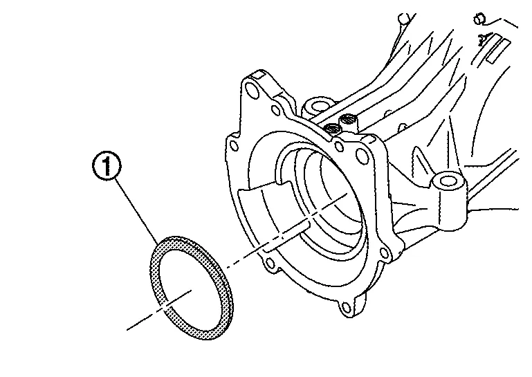
Remove wave spring.
Remove drive pinion oil seal from the inside of gear carrier. Refer to Disassembly and Assembly.
CAUTION:
When removing electric controlled coupling, replace drive pinion oil seal.
Remove connector bracket from electric controlled coupling.
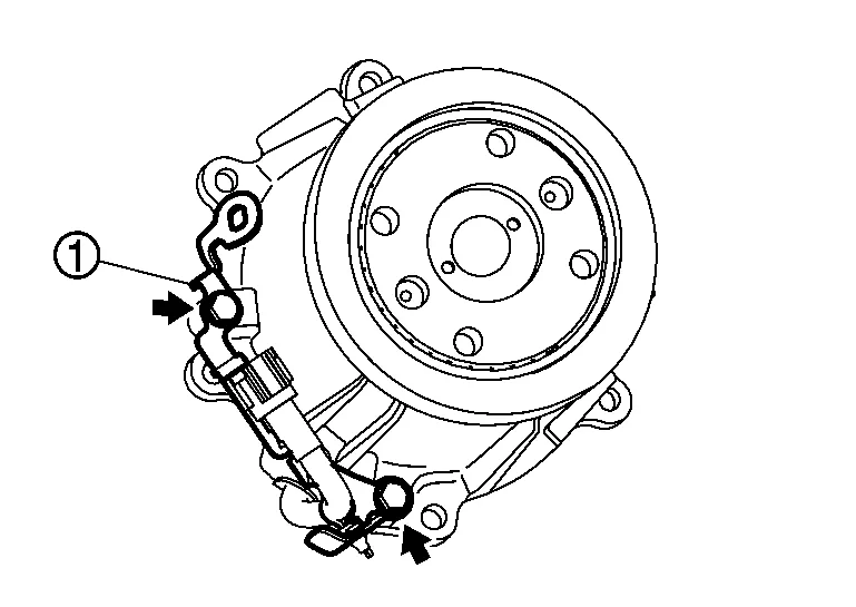
Separate connector clip from connector bracket.
ASSEMBLY
Install connector bracket to electric controlled coupling.
-
For tightening torque, refer to Exploded View.
Join AWD solenoid harness with connector clip.
Install drive pinion oil seal to the inside of gear carrier. Refer to Disassembly and Assembly.
CAUTION:
When removing electric controlled coupling, replace drive pinion oil seal.
Install wave spring to the inside of gear carrier.
Apply liquid gasket to mating surface of electric controlled coupling assembly.
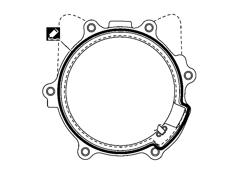
-
For applying liquid gasket, refer to Exploded View.
CAUTION:
-
Remove old gasket adhering to the mounting surfaces. Also remove any moisture, oil, or foreign material adhering to the mounting surfaces.
-
The width of sealant bead is approximately 3 mm (0.12 in). Apply sealant evenly.
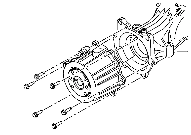
Match electric controlled coupling assembly to spline of drive pinion, then install it to final drive assembly .
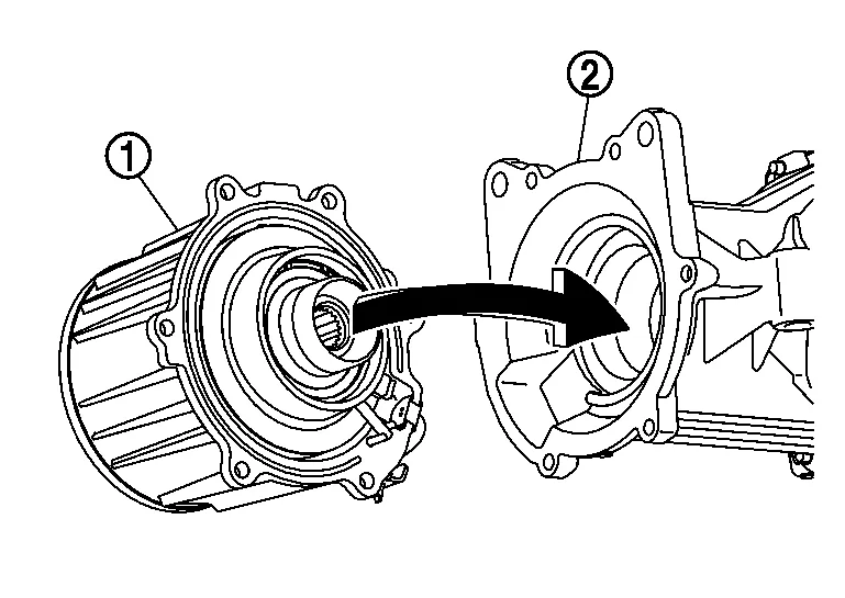
CAUTION:
Be careful not to damage drive pinion oil seal.
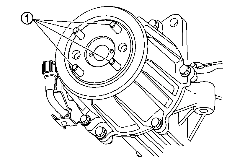
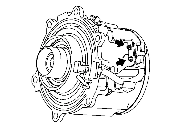
Temporarily tighten reamer bolts to the positions shown in the figure.
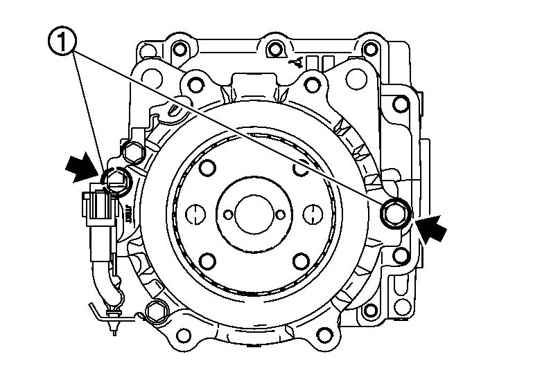
Tighten reamer bolts and electric controlled coupling assembly mounting bolts to the specified torque.
-
For tightening torque, refer to Exploded View.
Install stud bolts .
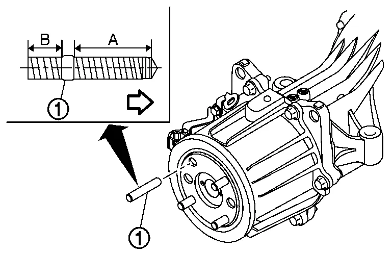
| : Electric controlled coupling side |
| Thread length | |
| A | : Long |
| B | : Short |
CAUTION:
-
Do not reuse stud bolt.
-
Screw long thread side of stud bolt to electric controlled coupling.
-
Screw the stud bolt until the stop by applying a torque of 15 N·m (1.5 kg-m, 11 ft-lb) ±20%.
-
After installing stud bolt, the length of the protrusion from electric controlled coupling must be 19.8 mm (0.780 in) ±1.4 mm (0.055 in).

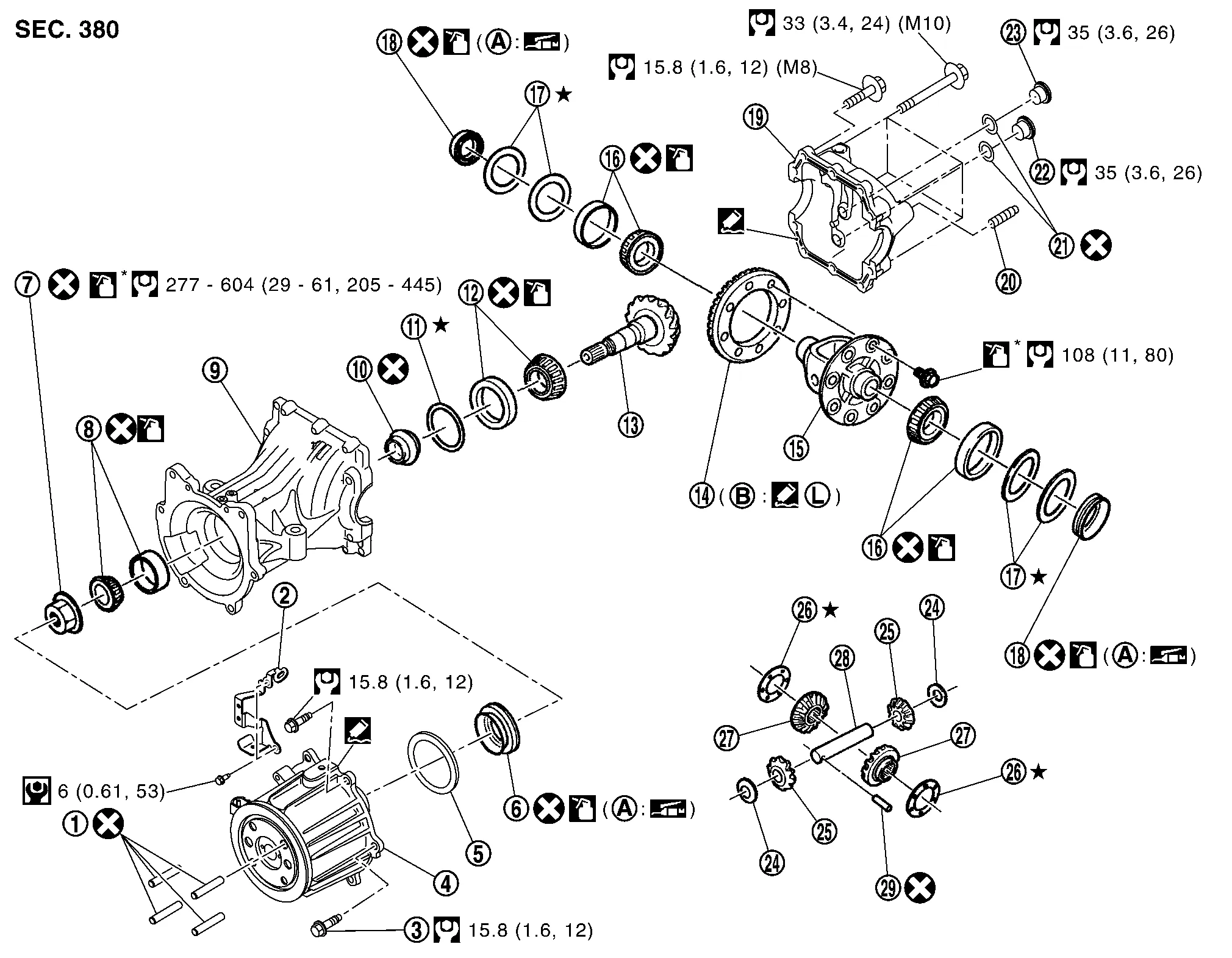
 Differential Assembly
Exploded View
Stud bolt
Connector bracket
Reamer bolt
Electric controlled coupling assembly
Wave spring
Drive pinion oil seal
Drive pinion lock nut
Pinion front bearing
Gear carrier
Collapsible spacer
Drive pinion adjusting shim
Pinion rear bearing
Drive pinion
Drive gear
Differential case
Side bearing
Side bearing adjusting shim
Side oil seal
Rear cover
Stud bolt
Gasket
Drain plug
Filler plug
Pinion mate thrust washer
Pinion mate gear
Side gear thrust washer
Side gear
Pinion mate shaft
Lock pin
Oil seal lip
Screw hole
: N·m (kg-m, in-lb)
: N·m (kg-m, ft-lb)
: Always replace after every disassembly...
Other information:
Nissan Murano (Z52) 2015-2024 Owners Manual: Headlights
For additional information on headlight bulb replacement, refer to the instructions outlined in this section. Replacing the halogen headlight bulb (if so equipped) If bulb replacement is required, it is recommended that you visit a NISSAN dealer for this service...
Nissan Murano (Z52) 2015-2024 Service Manual: Hood Lock Release Cable
Removal and Installation REMOVALRemove fender protector (LH). Refer to Removal and Installation. Remove front grille. Refer to Removal and Installation. Disconnect hood lock release cable from hood lock release handle and hood lock. Release hood lock release cable clips using a suitable tool...
Categories
- Manuals Home
- Nissan Murano Owners Manual
- Nissan Murano Service Manual
- GAS STATION INFORMATION
- Jacking up vehicle and removing the damaged tire
- Checking engine oil level
- New on site
- Most important about car
Luggage hooks

When securing items using luggage hooks located on the back of the seat or side finisher do not apply a load over more than 6.5 lbs. (29 N) to a single hook.
The luggage hooks that are located on the floor should have loads less than 110 lbs. (490 N) to a single hook.