Nissan Murano: Meter, Warning Lamp & Indicator :: System Description / Diagnosis System (combination Meter)
COMBINATION METER SELF-DIAGNOSIS MODE
The following meter functions can be checked during Combination Meter Self-Diagnosis Mode:
-
Pointer sweep of speedometer, tachometer and gauges
-
Illumination of all LCD segments and color patterns for meter displays
-
Illumination of all lamps/LEDs that are controlled by the combination meter (regardless of switch status)
STARTING COMBINATION METER SELF-DIAGNOSIS MODE
 NOTE:
NOTE:
-
Check combination meter power supply and ground circuits if self-diagnosis mode does not start. Refer to Diagnosis Procedure. Replace combination meter if power supply and ground circuits are found to be normal and self-diagnosis mode does not start. Refer to Removal and Installation.
-
Combination meter self-diagnosis mode will function with the ignition switch in ON. Combination meter self-diagnosis mode will exit upon placing the ignition switch to OFF.
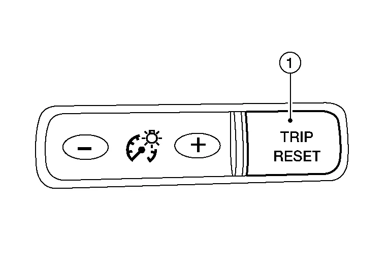
How to Initiate Self-Diagnosis Mode
-
Ignition switch OFF.
-
While pressing the trip reset switch (1), place ignition switch ON.
-
Keep pressing the trip reset switch for 1 second or more.
-
Press the trip reset switch at least 3 times within 7 seconds after the ignition switch is placed ON.
-
“Work instruction code” is indicated in the top portion of information display and self-diagnosis is started.
-
The mode switches in the order shown below each time the trip reset switch is pressed.
NOTE:
If the trip reset switch is not operated for 20 seconds or more, the self-diagnosis mode is automatically canceled.
| Test order | Test item | Description | |
|---|---|---|---|
| 1 | Work instruction code | This item is displayed, but not used. | |
| 2 | Part number | ||
| 3 | Software code | ||
| 4 | EEPROM code | ||
| 5 | Hardware code | ||
| 6 | P.C.B code | ||
| 7 | Circuit check |
The pointer of the following items moves from 0 to MAX twice.
If any of the pointers does not sweep, replace combination meter. |
|
| 8 | Color check | Performs the color check of the information display. | |
| 9 | Error code |
Displays the error code of the following items:
|
|
| 10 | Warning/indicator lamp check | All warning/indicator lamps illuminate. | |
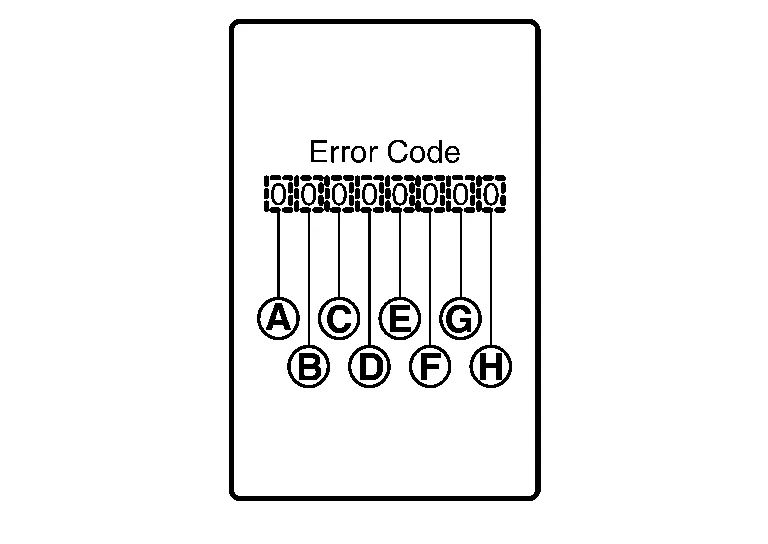
| Item | Code | Description | Action to take/Reference | |
|---|---|---|---|---|
 |
Speedometer | 0 | Normal | — |
| 1 | A Nissan Murano vehicle speed signal cannot be received from ABS actuator and electric unit (control unit). |
Select "Self Diagnostic Result" mode of “ABS”. Refer to DTC Index. |
||
| 2 | A Nissan Murano vehicle speed signal received from the ABS actuator and electric unit (control unit) is abnormal. | |||
 |
Tachometer | 0 | Normal | — |
| 1 | An engine speed signal cannot be received from ECM. |
Select "Self Diagnostic Result" mode of “ENGINE”. Refer to DTC Index. |
||
 |
Fuel gauge | 0 | Normal | — |
| 1 | Fuel gauge circuit is shorted. | Refer to Component Function Check. | ||
| 2 | Fuel gauge circuit is open. | |||
 |
Engine coolant temperature gauge | 0 | Normal | — |
| 1 | An engine coolant temperature signal cannot be received from ECM. |
Select "Self Diagnostic Result" mode of “ENGINE”. Refer to DTC Index. |
||
 |
Meter control switch | 0 | Normal | — |
| 1 | When judging that the illumination control switch signal circuit is shorted for 5 minutes or more. | Refer to Diagnosis Procedure. | ||
| 2 | When judging that the trip reset switch signal circuit is shorted for 5 minutes or more. | |||
| 3 | When judging that both switch signal circuit are shorted for 5 minutes or more. | |||
 |
— | 0 | Displays “0” constantly. | — |
 |
— | 0 | Displays “0” constantly. | — |
 |
— | 0 | Displays “0” constantly. | — |
How to Reset Error Code
Error codes stored in combination meter can be reset by following the instructions below:
-
Ignition switch OFF.
-
While pressing the trip reset switch, place ignition switch ON.
-
Keep pressing the trip reset switch for 1 second or more.
-
Press the trip reset switch at least 3 times within 7 seconds after the ignition switch is placed ON.
-
Ignition switch OFF.
-
Perform self-diagnosis and check that the error codes are reset.
APPLICATION ITEMS
CONSULT can display each diagnostic item using the diagnostic test modes shown.
| METER/M&A Diagnosis mode | Description | |
|---|---|---|
| Self Diagnostic Result | Displays combination meter self-diagnosis results. | |
| Data Monitor | Displays combination meter input/output data in real time. | |
| Work support | Displays diagnosis procedure of each work item. | |
| ECU Identification | Displays combination meter part number. | |
| Warning History | Lighting history of the warning lamp and indicator lamp can be checked. | |
| CAN DIAG SUPPORT MNTR | The result of transmit/receive diagnosis of CAN communication can be read. | |
SELF DIAG RESULT
Refer to DTC Index.
DATA MONITOR
NOTE:
The following table includes information (items) inapplicable to this Nissan Murano vehicle. For information (items) applicable to this vehicle, refer to CONSULT display items.
Display Item List
X: Applicable
| Display item [Unit] |
MAIN SIGNALS | Description |
|---|---|---|
|
SPEED METER [mph or km/h] |
X | Displays the value of Nissan Murano vehicle speed signal. |
|
SPEED OUTPUT [mph or km/h] |
X | Nissan Murano Vehicle speed signal value transmitted to other units via CAN communication. |
|
ODO OUTPUT [mph or km/h] |
Odometer signal value transmitted to other units via CAN communication. | |
|
TACHO METER [rpm] |
X | Value of the engine speed signal received from ECM via CAN communication. |
|
FUEL METER [L] |
X | Fuel level indicated on combination meter. |
|
W TEMP METER [°F] or [°C] |
X | Displays the value of engine coolant temperature signal, which is input from ECM. |
|
ABS W/L [On/Off] |
Displays [ON/OFF] condition of ABS warning indicator. | |
|
VDC/TCS IND [On/Off] |
Displays [ON/OFF] condition of VDC OFF indicator lamp. | |
|
SLIP IND [On/Off] |
Displays [ON/OFF] condition of SLIP indicator lamp. | |
|
BRAKE W/L [On/Off] |
Displays [ON/OFF] condition of brake warning indicator. | |
|
DOOR W/L [On/Off] |
Displays [ON/OFF] condition of door open warning message. | |
|
TRUNK/GLAS-H [On/Off] |
Displays [ON/OFF] condition of back door open warning message. | |
|
HI-BEAM IND [On/Off] |
Displays [ON/OFF] condition of high beam indicator. | |
|
TURN IND [On/Off] |
Displays [ON/OFF] condition of turn indicator. | |
|
LIGHT IND [On/Off] |
Displays [ON/OFF] condition of light indicator. | |
|
FR FOG IND [On/Off] |
Displays [ON/OFF] condition of front fog lamp indicator. | |
|
OIL W/L [On/Off] |
Displays [ON/OFF] condition of low oil pressure warning message in the information display. | |
|
MIL [On/Off] |
Displays [ON/OFF] condition of malfunction indicator. | |
|
BA W/L [On/Off] |
Displays [ON/OFF] condition of AEB warning lamp indicator. | |
|
ATC/T-AMT W/L [On/Off] |
Displays [ON/OFF] condition of CVT check warning message in the information display. | |
|
4WD W/L [On/Off] |
Displays [ON/OFF] condition of AWD warning message in the information display. | |
|
FUEL W/L [On/Off] |
Displays [ON/OFF] condition of low-fuel warning message in the information display. | |
|
WASHER W/L [On/Off] |
Displays [ON/OFF] condition of low washer fluid warning message in the information display. | |
|
AIR PRES W/L [On/Off] |
Displays [ON/OFF] condition of tire pressure warning lamp. | |
|
KEY G/Y W/L [On/Off] |
Displays [ON/OFF] condition of key green warning lamp. | |
|
EPS W/L [On/Off] |
Displays [ON/OFF] condition of EPS warning indicator. | |
| LCD | X | Displays the value of Intelligent Key system message indication. |
|
ACC TARGET [On/Off] |
Displays [ON/OFF] condition of Nissan Murano vehicle ahead detection indicator in the information display. | |
|
ACC DISTANCE [Off, Short, Middle, Long] |
Displays [Off, Short, Middle, Long] condition of set distance indicator in the information display. | |
|
SHIFT IND [P, R, N, D] |
Displays shift selector position. | |
|
FUEL CAP W/L [On/Off] |
Displays [ON/OFF] condition of loose fuel cap warning message in the information display. | |
|
M RANGE SW [On/Off] |
Status of manual mode switch. | |
|
NM RANGE SW [On/Off] |
Status of non-manual mode switch. | |
|
AT SFT UP SW [On/Off] |
Status of manual mode shift up switch. | |
|
AT SFT DWN SW [On/Off] |
Status of manual mode shift down switch. | |
|
PKB SW [On/Off] |
Displays [ON/OFF] condition of parking brake switch. | |
|
BUCKLE SW [On/Off] |
Displays [ON/OFF] condition of seat belt buckle switch LH. | |
|
BRAKE OIL SW [On/Off] |
Displays [ON/OFF] condition of brake fluid level switch. | |
|
DISTANCE [Mi] or [km] |
Displays distance to empty. | |
|
OUTSIDE TEMP [°F or °C] |
Displays the ambient air temperature which is input from the ambient sensor. | |
|
FUEL LOW SIG [On/Off] |
Displays [ON/OFF] condition of low-fuel warning signal. | |
|
STRG SW INPUT [SW 1-SW 10, NOT INPUT] |
Displays [SW 1-SW 10, NOT INPUT] condition of steering switches. | |
|
SONAR DET STATUS [On/Off] |
Displays [ON/OFF] condition of sonar detection area. | |
|
SONAR WARN [Off, SENSOR DEACTIVE, SENSOR ERROR] |
Displays [OFF, SENSOR DEACTIVE, SENSOR ERROR] condition of sonar warning. | |
|
SONAR DET DSP RC [On/Off] |
Displays [ON/OFF] condition of RC sonar detection display. | |
|
SONAR DET DSP AREA RC [On/Off] |
Displays [ON/OFF] condition of RC sonar detection area image. | |
|
SONAR DET DSP RL [On/Off] |
Displays [ON/OFF] condition of RL sonar detection display. | |
|
SONAR DET DSP AREA RL [On/Off] |
Displays [ON/OFF] condition of RL sonar detection area image. | |
|
SONAR DET DSP RR [On/Off] |
Displays [ON/OFF] condition of RR sonar detection display. | |
|
SONAR DET DSP AREA RR [On/Off] |
Displays [ON/OFF] condition of RR sonar detection area image. | |
|
SONAR DET DSP FC [On/Off] |
Displays [ON/OFF] condition of FC sonar detection display. | |
|
SONAR DET DSP AREA FC [On/Off] |
Displays [ON/OFF] condition of FC sonar detection area image. | |
|
SONAR DET DSP FL [On/Off] |
Displays [ON/OFF] condition of FL sonar detection display. | |
|
SONAR DET DSP AREA FL [On/Off] |
Displays [ON/OFF] condition of FL sonar detection area image. | |
|
SONAR DET DSP FR [On/Off] |
Displays [ON/OFF] condition of FR sonar detection display. | |
|
SONAR DET DSP AREA FR [On/Off] |
Displays [ON/OFF] condition of FR sonar detection area image. | |
|
SONAR DIST DSP [On/Off] |
Displays sonar distance status. | |
|
BUZZER [On/Off] |
X | Buzzer status (in the combination meter) is detected from the buzzer output signal received from each unit via CAN communication and the warning output condition of the combination meter. |
|
TPMS PRESS L [On/Off] |
Displays [ON/OFF] condition of tire pressure low message in the information display. | |
|
4WD CL TMP H [On/Off] |
Displays [ON/OFF] condition of AWD system warning (AWD high temp) detected from AWD warning display error signal is received from AWD control unit via CAN communication. | |
|
4WD TIRE CHCK [On/Off] |
Displays [ON/OFF] condition of AWD system warning (tire size incorrect) detected from AWD warning display error signal is received from AWD control unit via CAN communication. | |
|
4WD SYS MALF [On/Off] |
Displays [ON/OFF] condition of AWD system warning (AWD error) detected from AWD warning display error signal is received from AWD control unit via CAN communication. | |
|
ASCD SPD BLNK [On/Off] |
Blinking status of ASCD set Nissan Murano vehicle speed judged by the ASCD status signal received from ECM via CAN communication. | |
|
ASCD STATUS [Off, ASCD, CRUISE] |
Status of ASCD status display judged by the ASCD status signal received from ECM via CAN communication. | |
|
ASCD REQ SPD [km/h/Off] |
ASCD set Nissan Murano vehicle speed value judged by the ASCD status signal received from ECM via CAN communication. | |
|
TPMS DISP [Not suport, HIGH, MEDIUM, LOW] |
Status of tire pressure low from tire pressure data signal is received from BCM via CAN communication. | |
|
TIRE STATUS FR [On/Off] |
Status of tire pressure data signal (front RH) from BCM via CAN communication. | |
|
TIRE STATUS FL [On/Off] |
Status of tire pressure data signal (front LH) from BCM via CAN communication. | |
|
TIRE STATUS RR [On/Off] |
Status of tire pressure data signal (rear RH) from BCM via CAN communication. | |
|
TIRE STATUS RL [On/Off] |
Status of tire pressure data signal (rear LH) from BCM via CAN communication. | |
|
LDW IND [On/Off] |
Status of LDW system display detected from meter display signal is received from ADAS control unit via CAN communication. | |
|
SET LDW [On/Off/Not support] |
Status of LDW system setting. | |
|
SET BSW [On/Off/Not support] |
Status of BSW system setting. | |
|
TIRE PRESS FR [kPa, kg/cm2 or Psi] |
The data of front RH tire pressure from BCM via CAN communication. | |
|
TIRE PRESS FL [kPa, kg/cm2 or Psi] |
The data of front LH tire pressure from BCM via CAN communication. | |
|
TIRE PRESS RR [kPa, kg/cm2 or Psi] |
The data of rear RH tire pressure from BCM via CAN communication. | |
|
TIRE PRESS RL [kPa, kg/cm2 or Psi] |
The data of rear LH tire pressure from BCM via CAN communication. | |
|
BSW IND [On/Off] |
Displays [ON/OFF] condition of blind spot warning indicator. | |
|
LDP IND [On/Off] |
Displays [Off, Short, Middle, Long] status of set distance indicator in the information display. | |
|
HI-BEAM ASST IND [mph/Off] |
Displays [ON/OFF] condition of high beam assist indicator lamp from high beam assist indicator lamp signal is received from BCM via CAN communication. |
WORK SUPPORT
| Work support item | Description |
|---|---|
| Outside air temperature diagnosis | A possible malfunction can be narrowed down by following the displayed instructions. |
| Fuel meter diagnosis(Analog pointer) | |
| Warning lamp diagnosis |
ECU IDENTIFICATION
Combination meter part number can be read.
WARNING HISTORY
Special menu
| Display item | Description |
|---|---|
| W/L ON HISTORY | Lighting history of warning lamp and indicator lamp can be checked. |
W/L ON HISTORY
-
“W/L ON HISTORY” indicates the “TIME” when the warning/indicator lamp is turned on.
-
The “TIME” above is:
-
0: The condition that the warning/indicator lamp has been turned on 1 or more times after starting the engine and waiting for 30 seconds.
-
1 - 39: The number of times the engine was restarted after the 0 condition.
-
NO W/L ON HISTORY: No warning/indicator lamp history is stored.
-
NOTE:
-
“W/L ON HISTORY” is not stored for approximately 30 seconds after the engine starts.
-
Brake warning lamp does not store any history when the parking brake is applied or the brake fluid level gets low.
 Operation
Switch Name and Function
STEERING SWITCHES No. Switch name Operation Description
1.
Enter/Up/Down switch
Press
The information display settings can be changed...

Other information:
Nissan Murano (Z52) 2015-2024 Owners Manual: Readiness for Inspection/Maintenance (I/M) test
WARNING A vehicle equipped with All -Wheel Drive (AWD) should never be tested using a two wheel dynamometer (such as the dynamometers used bysomestates for emissions testing), or similar equipment. Make sure you inform the test facility personnel that your vehicle is equipped with AWD before it is placed on a dynamometer...
Nissan Murano (Z52) 2015-2024 Service Manual: Center Pillar Lower Finisher
Removal and Installation REMOVALMove front seat to full forward position. Remove front kicking plate. Refer to Removal and Installation - Front Kicking Plate. Remove rear kicking plate. Refer to Removal and Installation - Rear Kicking Plate. Release center pillar lower finisher clips and pawls using a suitable tool and remove...
Categories
- Manuals Home
- Nissan Murano Owners Manual
- Nissan Murano Service Manual
- High Beam Assist (if so equipped)
- Intelligent Forward Collision Warning (I-FCW)
- Fuel recommendation
- New on site
- Most important about car
LATCH (Lower Anchors and Tethers for CHildren) system

LATCH system lower anchor locations - bench seat
Your vehicle is equipped with special anchor points that are used with LATCH system compatible child restraints. This system may also be referred to as the ISOFIX or ISOFIX compatible system. With this system, you do not have to use a vehicle seat belt to secure the child restraint unless the combined weight of the child and child restraint exceeds 65 lbs. (29.5 kg). If the combined weight of the child and child restraint is greater than 65 lbs. (29.5 kg), use the vehicle’s seat belt (not the lower anchors) to install the child restraint. Be sure to follow the child restraint manufacturer’s instructions for installation.