Nissan Murano: System Description / Component Parts. Rear View Monitor System
| No. | Component | Function |
|---|---|---|
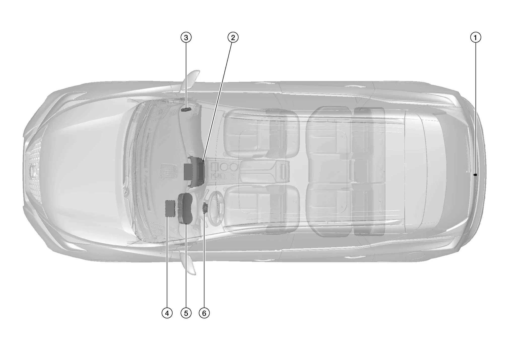
| 1. | Rear view camera | Refer to Rear View Camera. |
| 2. | Audio unit | Refer to Audio Unit. |
| 3. | Sonar control unit | Refer to Sonar Control Unit. |
| 4. | BCM (Body Control Module) | Refer to BCM. |
| 5. | Combination meter | Refer to Combination Meter. |
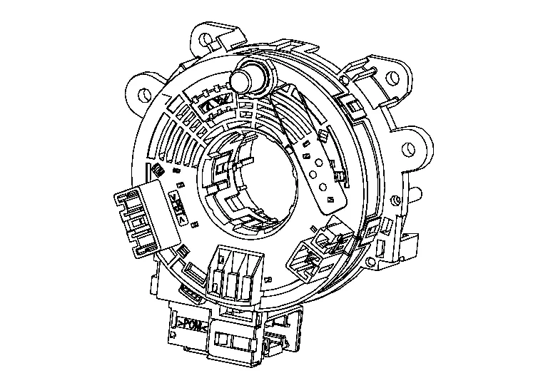
| 6. | Steering angle sensor | Refer to Steering Angle Sensor. |
-
A 8-inch color display with multi-touch control, an AM/FM HD electronic tuner radio with RDS, CD drive, audio amplifier and camera controller are integrated into the audio unit.

-
The 8-inch color display is a high resolution monitor that includes touch panel functions.
-
The rear view camera is installed next to the license plate lamp.

-
Power for the camera is supplied from the audio unit, and the image at the rear of the Nissan Murano vehicle is sent to the audio unit display.
The combination meter supplies the speed signal to the audio unit via CAN communication.

BCM sends the reverse signal to the audio unit.

-
Steering angle sensor is installed to the spiral cable.
-
Steering angle sensor sends the steering signal necessary for predictive course line to the audio unit via CAN communication.

 System
System Description
SYSTEM DIAGRAMAudio Unit Input Signal (CAN Communication) Transmit unit Signal name
BCM
Door switches state signal
Combination meter
Nissan Murano Vehicle speed signal
Steering angle sensor
Steering angle signal
Sonar control unit
Sonar detection display request signal
DESCRIPTIONOperation Description
When the selector lever is shifted to the reverse position, the rear view monitor image is displayed...
Categories
- Manuals Home
- Nissan Murano Owners Manual
- Nissan Murano Service Manual
- Turning the AEB system on/off
- Shift lock release
- Memory storage function (key-link)
- New on site
- Most important about car
Seatback pockets

Theremaybe one or two seatback pockets located on the back of the driver and passenger seats. The pockets can be used to store maps.
WARNING