Nissan Murano: Back Door / Back Door Assembly
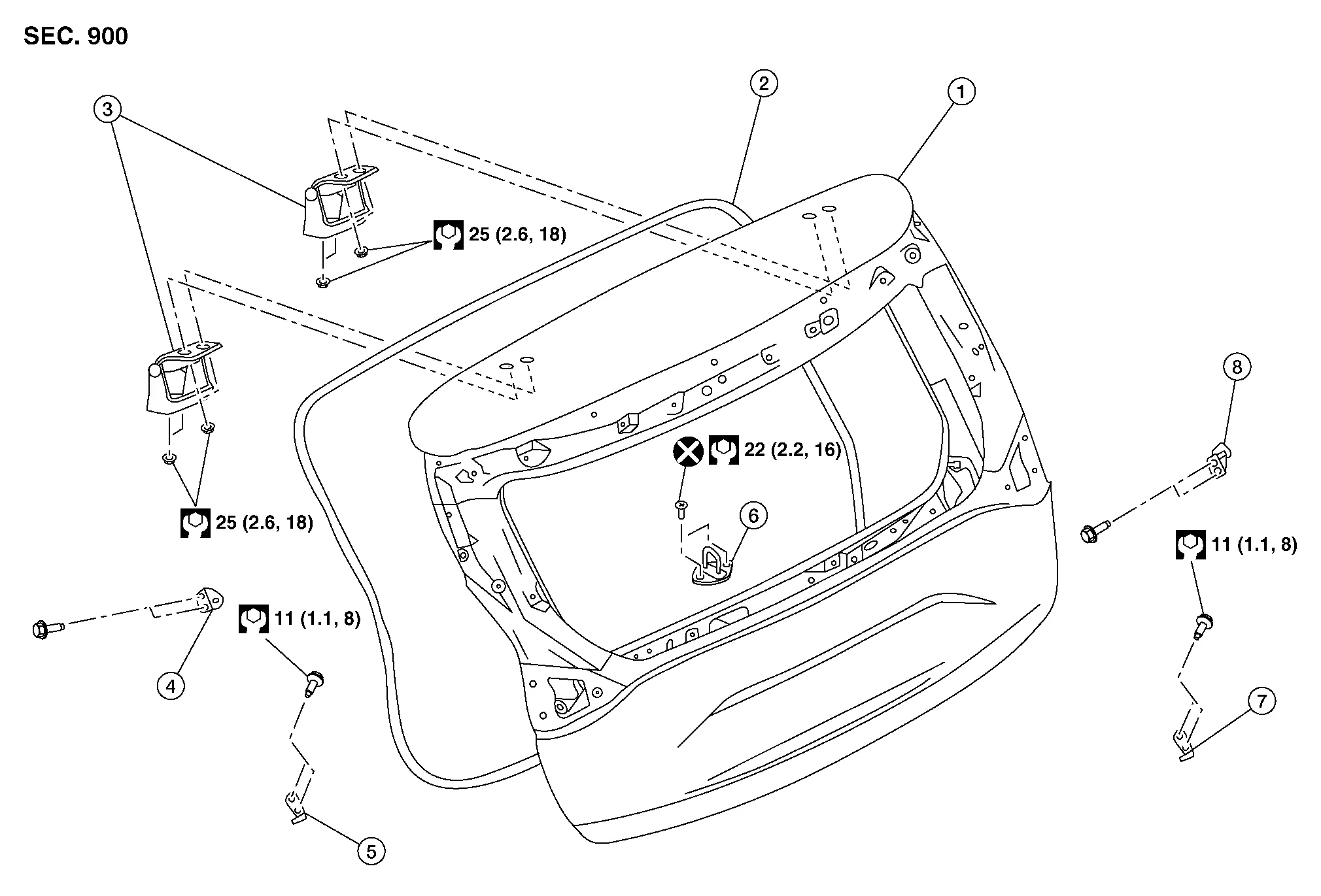
| 1. | Back door | 2. | Back door weather stripping | 3. | Back door hinge (LH/RH) |
| 4. | Back door upper stud ball or spindle unit upper hinge (with power back door) (LH) | 5. | Back door lower stud ball or spindle unit lower hinge (with power back door) (LH) | 6. | Back door striker |
| 7. | Back door lower stud ball or spindle unit upper hinge (with power back door) (RH) | 8. | Back door upper stud ball or spindle unit lower hinge (with power back door) (RH) |
CAUTION:
-
Use two people when removing or installing back door due to its heavy weight.
-
Use shop cloths to protect surrounding components from damage during removal and installation of back door.
REMOVAL
Support back door assembly using a suitable tool.
WARNING:
Bodily injury may occur if back door assembly is not supported properly when removing back door spindle unit.
Disconnect spindle units (LH/RH) or back door upper stud balls (LH/RH) from back door assembly. Refer to Removal and Installation (WITH AUTOMATIC BACK DOOR) or Removal and Installation (WITHOUT AUTOMATIC BACK DOOR).
Disconnect the harness connectors from the back door.
Remove back door harness grommet then pull harness from back door.
Disconnect washer tube.
Remove washer tube grommet and washer tube from back door.
Remove back door hinge bolts (door side) and back door assembly.
INSTALLATION
Installation is in the reverse order of removal.
CAUTION:
-
Tighten bolts to specification. Refer to Exploded View.
-
Apply anticorrosive agent onto surface between hinge and door side.
-
When reusing stud ball, always apply locking sealant before installing stud ball to back door.
-
When installing back door harness grommet be sure that back door harness is properly seated or damage will occur.
-
After installation, perform back door assembly adjustment procedure. Refer to Adjustment.
-
Perform camera image calibration (with around view monitor). Refer to Description (WITH DISPLAY AUDIO) or Description (WITH NAVIGATION).
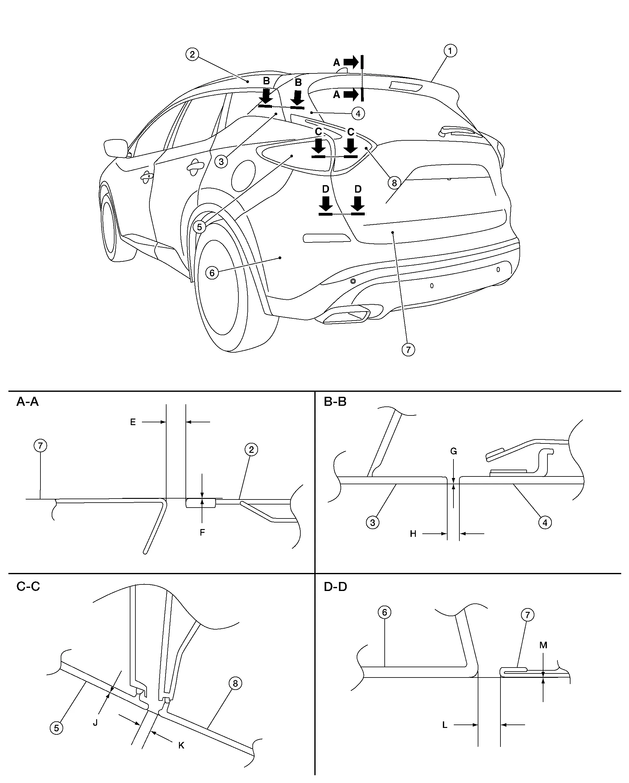
| 1. | Rear spoiler | 2. | Roof | 3. | Quarter window finisher |
| 4. | Side air spoiler | 5. | Rear combination lamp | 6. | Rear bumper |
| 7. | Back door | 8. | Back-up lamp |
Check clearance and surface height between back door and each part by visual inspection and tactile feel. If clearance and surface height are out of specification, adjust them according to adjustment procedure.
Unit: mm (in)
| Portion | Section | Item | Measurement | Standard | Parallelism |
|---|---|---|---|---|---|
| Spoiler – Roof | A – A | E | Clearance | 6.0 ± 1.0 (0.24 ± 0.04) | 1.5 (0.06) |
| F | Surface height | 0.3 ± 1.0 (0.01 ± 0.04) | 1.5 (0.06) | ||
| Quarter window finisher – Side air spoiler | B – B | G | Clearance | 3.0 ± 2.4 (0.12 ± 0.09) | 1.9 (0.07) |
| H | Surface height | — | — | ||
| Rear combination lamp – Back-up lamp | C – C | J | Clearance | 5.0 ± 2.0 (0.18 ± 0.08) | 2.0 (0.08) |
| K | Surface height | — | — | ||
| Rear bumper – Back door | D – D | L | Clearance | 6.0 ± 1.9 (0.19 ± 0.08) | 2.0 (0.08) |
| M | Surface height | 0.5 ± 1.9 (0.02 ± 0.07) | — |
Loosen back door hinge nuts (door side).
Lift up back door approximately 100 – 150 mm (3.94 – 5.91 in) height then close it lightly and check that it is engaged firmly with back door closed.
Check clearance and surface height according to specifications provided.
Tighten back door hinge nuts to specified torque.
CAUTION:
-
After installation, check back door open/close and lock/unlock operation.
-
Check back door hinge rotating point for poor lubrication. If necessary, apply a suitable multi-purpose grease.
-
After adjusting, apply touch-up paint (body color) to heads of rear door hinge bolts and nuts.
-
Perform calibration of automatic back door position information. Refer to Description.
 Back Door
..
 Back Door Striker
Removal and Installation
REMOVALRemove back door kicking plate. Refer to Removal and Installation.
Remove bolts and back door striker.INSTALLATIONInstallation is in the reverse order of removal...
Other information:
Nissan Murano (Z52) 2015-2024 Service Manual: Front Wiper Blade
Exploded View 1. Front wiper blade (RH) 2. Front wiper arm (RH) 3. Front wiper arm cover (RH) 4. Front wiper arm cover (LH) 5. Front wiper arm (LH) 6. Front wiper blade (LH) Removal and Installation REMOVALLift the front wiper arm and blade assembly away from the windshield glass...
Nissan Murano (Z52) 2015-2024 Service Manual: I-Li
Work Procedure Description Perform action test to verify the customer's concern. Perform action test and check the system operation after system diagnosis. WARNING: Be careful of traffic conditions and safety around the vehicle when performing road test...
Categories
- Manuals Home
- Nissan Murano Owners Manual
- Nissan Murano Service Manual
- Fuel recommendation
- Shift lock release
- Passenger compartment
- New on site
- Most important about car
Luggage hooks

When securing items using luggage hooks located on the back of the seat or side finisher do not apply a load over more than 6.5 lbs. (29 N) to a single hook.
The luggage hooks that are located on the floor should have loads less than 110 lbs. (490 N) to a single hook.